7
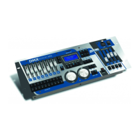
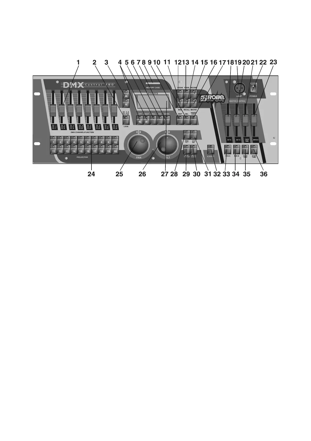
4.Control elements of the controller
Top panel:
1 - DMX CHANNEL/FUNCTION sliders
Every slider represents a DMX-channel of the respective projector and can be individually assigned.
Please take the DMX channel-occupation from the user manual of the respective projector.
2 - CHANNEL RANGE/LOCK button
The button determines the channel range for DMX CHANNEL/FUNCTION sliders or locks the controller.
3 - UP/DOWN buttons
By pressing the buttons you can adjust the desired value on the display.
4 -LEFT/RIGHT buttons
By pressing the buttons you can move between editable items on the display.
5 - MENU button
The button accesses the main menu.
6 - ESCAPE button
For return to the main menu or submenu.
7 - ENTER button
Confirming button
8 - MEMORY CARD slot
9 - NEXT/GROUP button
Function depends on menu where the button is used.
10 - INSERT/COPY button
Function depends on menu where the button is used.
11 - MANUAL button
For manual control of the selected projector.
12 - SCENE button
For scene running.
13 - PROGRAM button
For program running.
14 - RECALL button
Function depends on menu, where the button is used.
15 - RECORD button
For record running.
16 - MACRO button
17 - DELETE/CHASER button
Function depends on menu where the button is used.
18 - INT A slider
A slider for adjusting the light intensity of program(scene,record) running A.
19 - DESK LAMP socket
The 3 pin XLR socket for gooseneck lamp contains 12V AC ; pin 1=not connected
 Loading...