Installation
20220596E 97
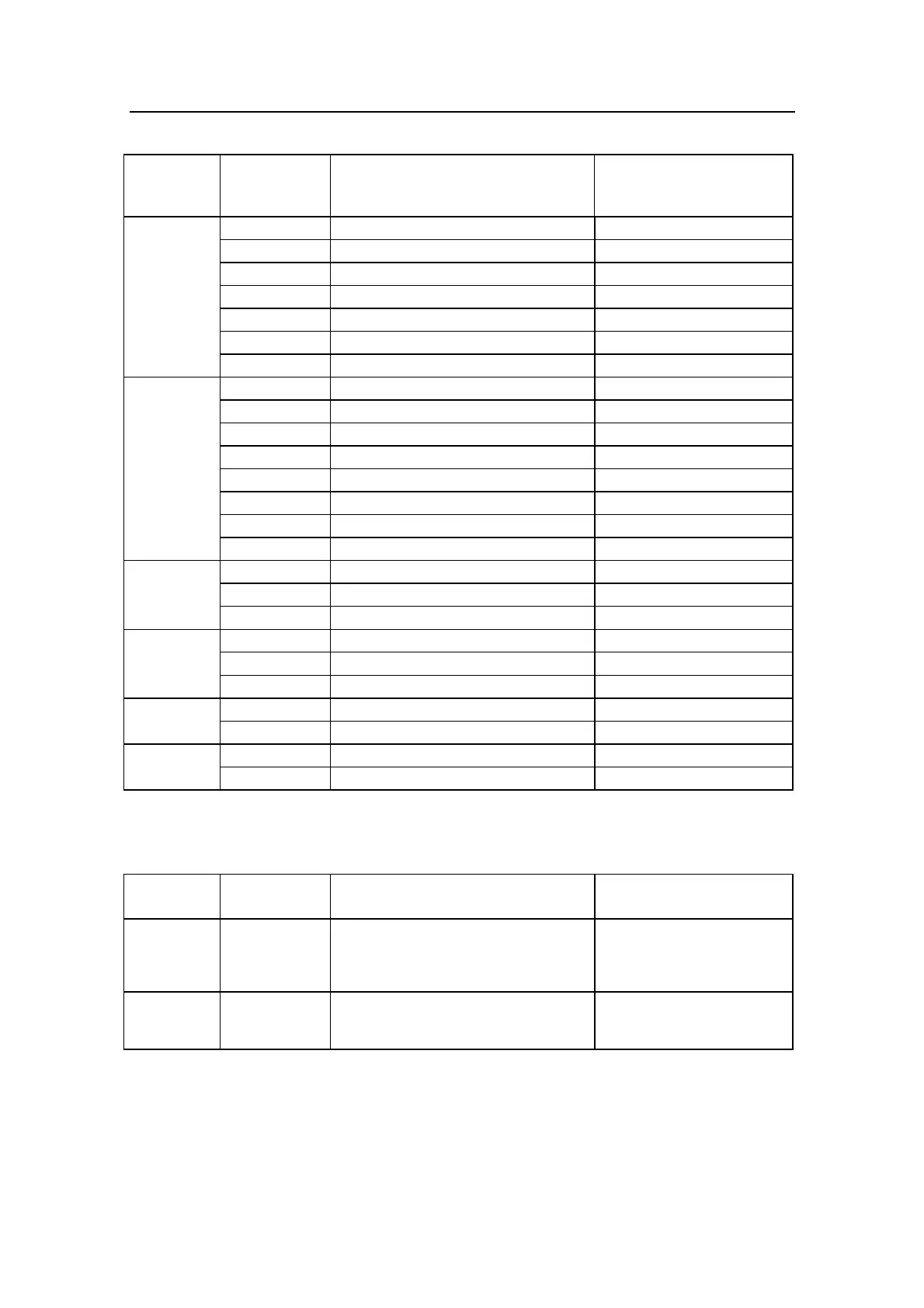
Setup item
(abbrev.
name)
Equipment
connected
Hardware port terminal
(use one available from list)
Hardware port
to be assigned
(* = default setting)
NAV2 Not connected – – – –*
J300X, Main PCB NMEA I/P RX1+,RX1– J300X-1
J300X, Power PCB NMEA I/P RX2+,RX2– J300X-2
NI300X, NMEA port #1 NI300-1
NI300X, NMEA port #2 NI300-2
NI300X, NMEA port #3 NI300-3
NI300X, NMEA port #4 NI300-4
INSTR Not connected – – – –
WIND J3XX, Main PCB NMEA I/P RX1+,RX1– J300X-1*
J300X, Power PCB NMEA I/P RX2+,RX2– J300X-2
NI300X, NMEA port #1 NI300-1
NI300X, NMEA port #2 NI300-2
NI300X, NMEA port #3 NI300-3
NI300X, NMEA port #4 NI300-4
CI300X, sin/cos/Gnd CI300X
RFC Not connected – – – –
RFC35 Junction unit: HS+, HS– J300X *
RFC35R Connection to ROBNET ROBNET
MAGN Not connected – – – –*
CDI35+CD100 Junction unit: HS+, HS– J300X
CD100 CI300X Magn. Comp. terminal CI300X
FLUXG Not connected – – – –*
CI300X Analogue terminal CI300X
GYRO Not connected – – – –*
RGC50, RGC10 CI300X Gyro terminal CI300X
J3XX = All junction unit models
Interface setup - Output signal
Setup item Output signal Output terminal Select output
(* = default setting)
Output
INSTR
High speed
NMEA output of
compass
heading
Junction unit Main PCB,
NMEA, TX1+, TX1–
J300X-1 * 5x/second
– 1x/second
Output
RADAR
Clock/data
heading output
to radars
J300X Power PCB, TB9 Anritsu *
Furuno
The Interface Menu presents these names so that they can be
assigned to a hardware input or output port. Each abbreviated
name is then presented in appropriate locations of the USER