EasyManua.ls Logo

Rockwell Automation Allen-Bradley PowerFlex 700S - Page 129

Rockwell Automation Allen-Bradley PowerFlex 700S
148 pages
To Next Page IconTo Next Page
To Previous Page IconTo Previous Page
Loading...
Rockwell Automation Publication 750-RM004A-EN-P - April 2018 129
Enclosure Information Appendix A
Figure 39 - Frame 8 PowerFlex 755TL/TR
335 (13.2)
400 (15.7)
867.5 (34.2)
967.5 (38.1)
1135 (44.7)
1067.5 (42.0)
0 (0)
451
(17.8)
45
(1.8)
709
(27.9)
1206
(47.5)
400
(15.7)
800
(31.5)
49
(1.9)
153
(6.0)
36
(1.4)
150
(5.9)
105
(4.1)
535
(21.1)
1407
(55.4)
IP21, UL Type 1
2132
(83.9)
IP54, UL Type 12
2291
(90.2)
IP21, UL Type 1
676
(26.6)
IP54, UL Type 12
721
(28.4)
48
(1.9)
301
(11.9)
128
(5.0)
90
(3.5)
312
(12.3)
200
(7.9)
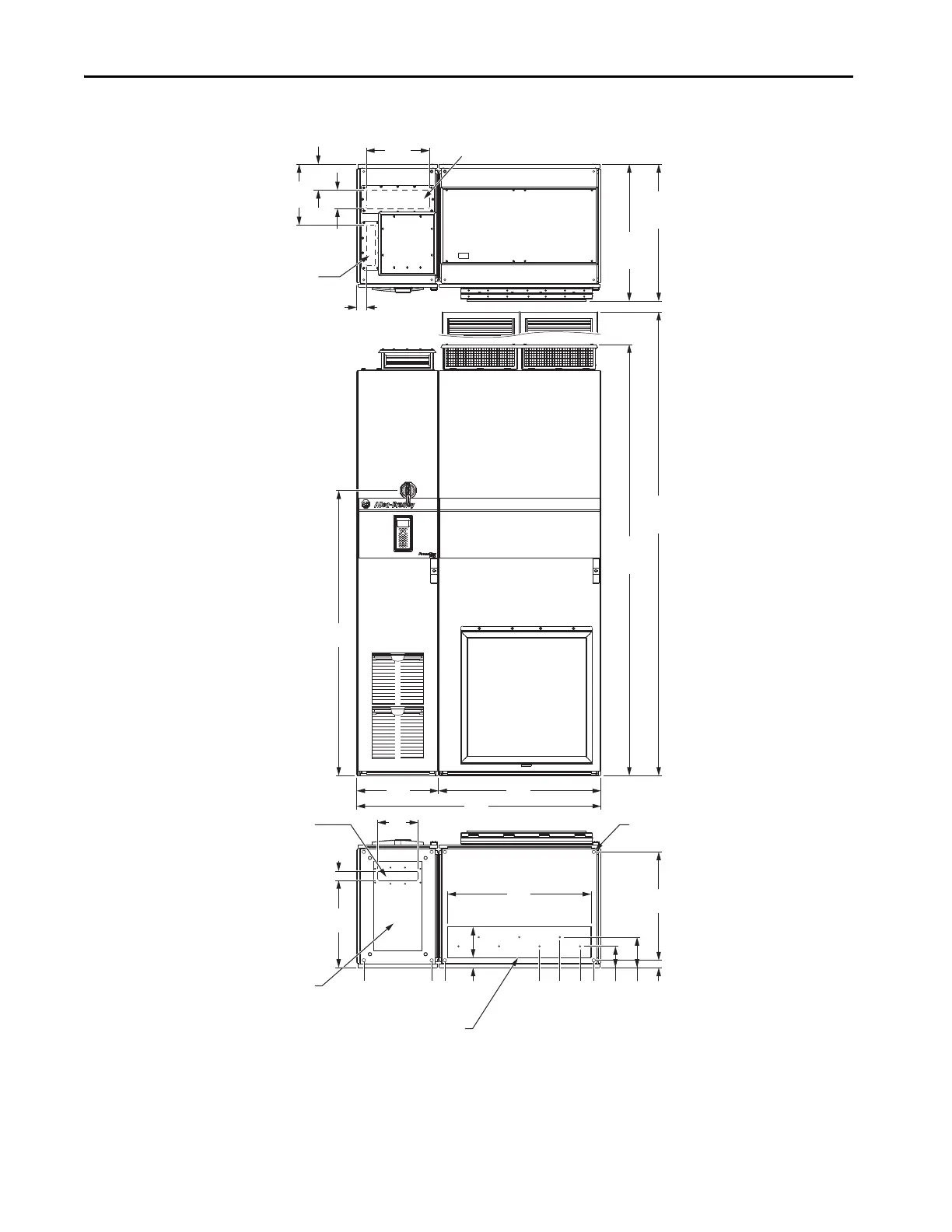
Input Power Cables - Top Entry
Signal Cables - Top Entry
Dimensions same as bottom.
Motor Cables - Bottom Exit
(Plate is marked with recommended gland or conduit hole pattern.)
Power Bay
Input Bay
Signal Cables - Bottom Entry
Input Power Cables - Bottom Entry
Mounting Holes

Table of Contents

Other manuals for Rockwell Automation Allen-Bradley PowerFlex 700S

Related product manuals