130 Rockwell Automation Publication 750-RM004A-EN-P - April 2018
Appendix A Enclosure Information
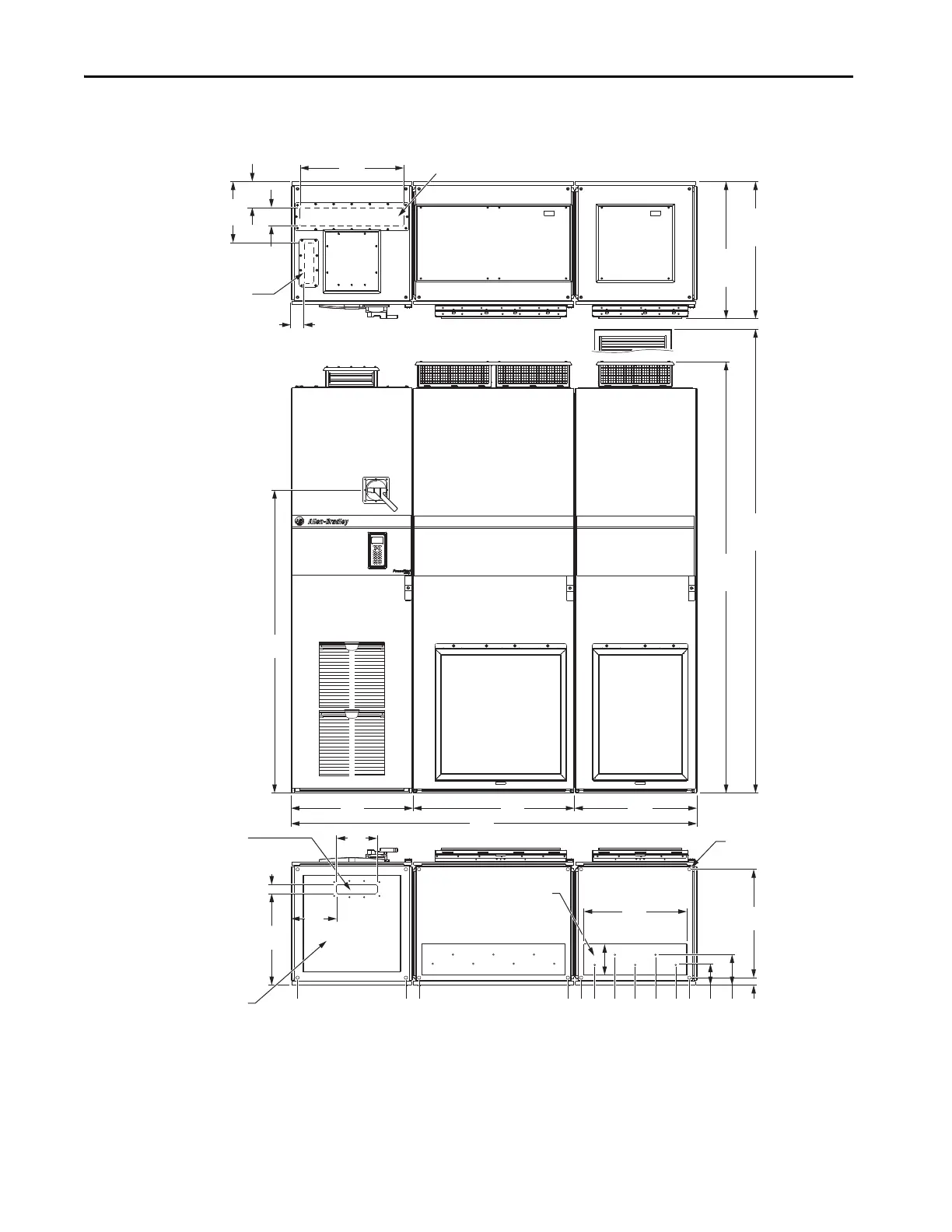
Figure 40 - Frame 9 PowerFlex 755TL/TR
0 (0)
535 (2.1)
600 (23.6)
1335 (52.6)
1935 (76.2)
1400 (55.1)
1668 (65.7)
1768 (69.6)
1868 (73.5)
1468 (57.8)
1568 (61.7)
431
(17.0)
45
(1.8)
200
(7.9)
2006
(79.0)
600
(23.6)
800
(31.5)
600
(23.6)
509
(20.0)
153
(6.0)
1495
(58.9)
IP21, UL Type 1
2132
(83.9)
IP54, UL Type 12
2291
(90.2)
IP21, UL Type 1
676
(26.6)
IP54, UL Type 12
721
(28.4)
66
(2.6)
301
(11.9)
128
(5.0)
90
(3.5)
512
(20.2)
225
(8.9)
36
(1.4)
150
(5.9)
105
(4.1)
535
(21.1)
Input Power Cables - Top Entry
Signal Cables - Top Entry
Dimensions same as bottom.
Mounting Holes
Power BayInput Bay
Signal Cables - Bottom Entry
Input Power Cables - Bottom Entry
Motor Cables - Bottom Exit
(Plate is marked with
recommended gland or
conduit hole pattern.)
Power Bay
 Loading...


