PowerFlex 700H Control Wiring 2-5
Analog I/O Configuration
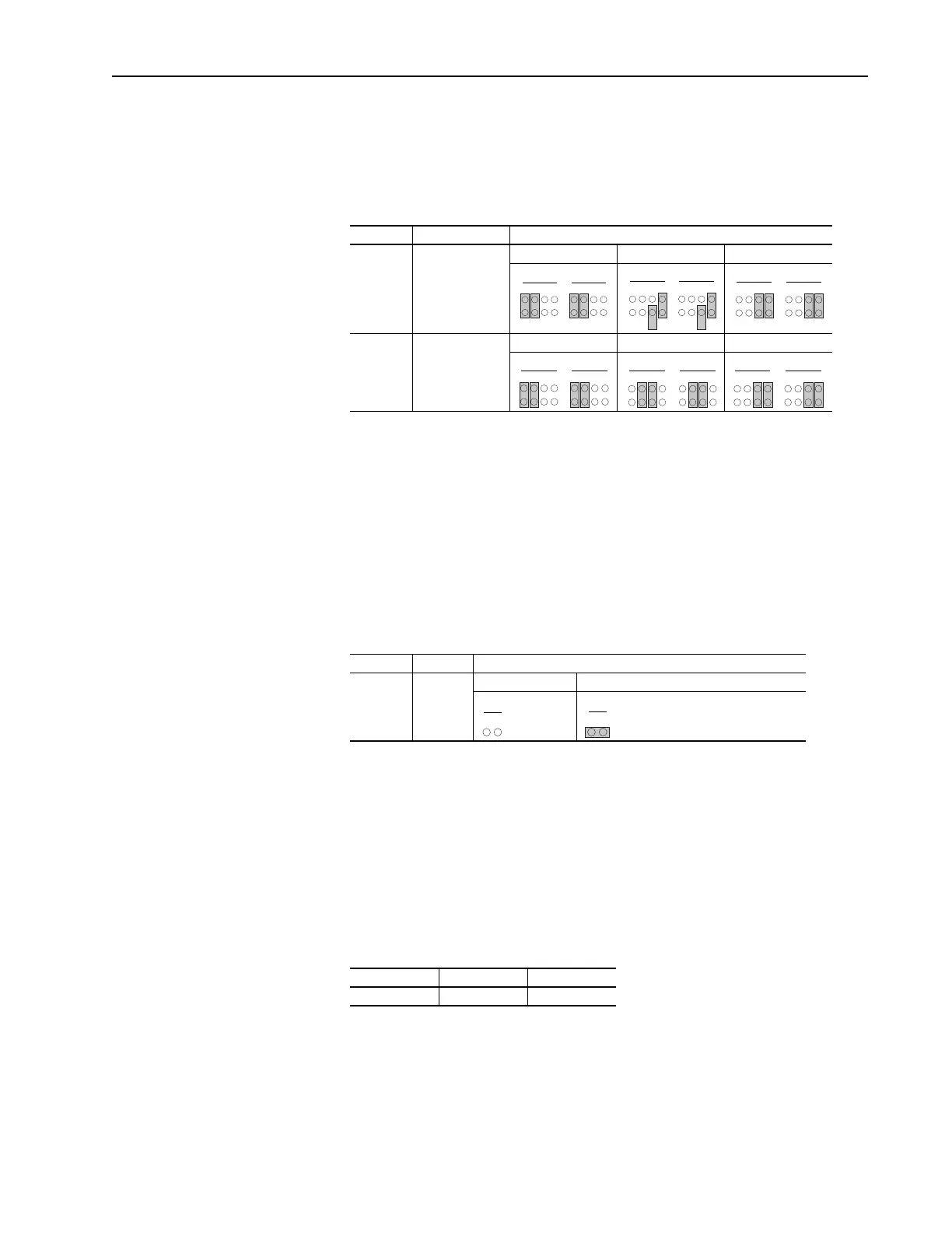
Important: Analog I/O must be configured through programming, as well
as the jumpers shown below.
Figure 2.3 I/O Configuration
Hardware Enable Circuitry
By default, the user can program a digital input as an Enable input. The
status of this input is interpreted by drive software. If the application
requires the drive to be disabled without software interpretation, a
“dedicated” hardware enable configuration can be utilized. This is done by
removing jumper J5 and wiring the enable input to “Digital In 6” (see
below). Verify that [Digital In6 Sel], parameter 366 is set to “1, Enable.”
Figure 2.4 Hardware Enable Configuration
Auxiliary Power Supply
You may use an auxiliary power supply to keep the 700H Control Unit
energized, when input power is de-energized. This provides back-up power
for the Control Unit and is sufficient for setting parameters. Connect 24V dc
power to pin 19 and 24V dc common to pin 20 of the 24V dc version of the
I/O card.
Auxiliary Power Supply Specifications
Signal Jumper Setting
Analog
Inputs
J1 (Analog In 1)
J2 (Analog In 2)
0-20 mA 0-10V ±10V
Analog
Outputs
J3 (Analog Out 1)
J4 (Analog Out 2)
0-20 mA 0-10V ±10V
Signal Jumper Setting
Hardware
Enable
J5 Hardware Enable Input Programmable (No Hardware Enable)
Voltage Current (Min) Current (Max)
24V dc ± 15% 150 mA 250 mA
CDBA
J1 J2
CDBA
CDBA
J1 J2
CDBA
CDBA
J1 J2
CDBA
CDBA
J3 J4
CDBA
CDBA
J3 J4
CDBA CDBA
J3 J4
CDBA
BA
J5
BA
J5
 Loading...


