2-6 PowerFlex 700H Control Wiring
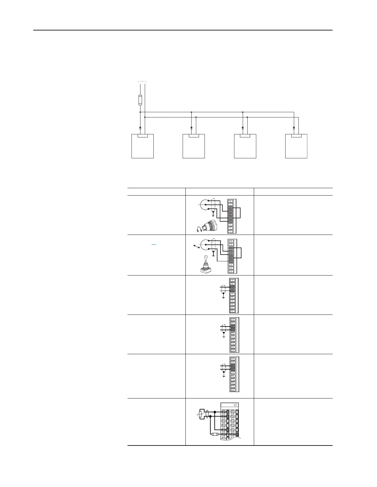
If 24V terminals of several drives are connected in parallel, we recommend
using a diode circuit to block current flow in the opposite direction. Reverse
current flow could damage the Control Board.
I/O Wiring Examples
Input/Output Connection Example Required Parameter Changes
Potentiometer Unipolar
Speed Reference
(1)
10k Ohm Pot.
Recommended
(2k Ohm Minimum)
• Adjust Scaling:
Parameters 91/92 and 325/326
• View Results:
Parameter 002
Joystick Bipolar Speed
Reference
(1)
±10V Input
• Set Direction Mode:
Parameter 190 = “1, Bipolar”
• Adjust Scaling:
Parameters 91/92 and 325/326
• View Results:
Parameter 002
Analog Input Bipolar
Speed Reference
±10V Input
• Set Direction Mode:
Parameter 190 = “1, Bipolar”
• Adjust Scaling:
Parameters 91/92 and 325/326
• View Results:
Parameter 002
Analog Voltage Input
Unipolar Speed
Reference
0 to +10V Input
• Configure Input with parameter 320
• Adjust Scaling:
Parameters 91/92 and 325/326
• View results:
Parameter 002
Analog Current Input
Unipolar Speed
Reference
4-20 mA Input
• Configure Input for Current:
Parameter 320 and add jumper at
appropriate terminals
• Adjust Scaling:
Parameters 91/92 and 325/326
• View results:
Parameter 002
Analog Input, PTC
PTC OT set > 5V
PTC OT cleared < 4V
PTC Short < 0.2V
• Set Drive Alarm 1:
Parameter 211, bit 11 = “True”
• Set Fault Config 1:
Parameter 238, bit 7 = “Enabled”
• Set Alarm Config 1:
Parameter 259, bit 11 = “Enabled”
:19 :20
From Auxiliary
Power Supply
:19 :20 :19 :20 :19 :20
24V dc
Power
24V dc
Common
3
4
6
6
7
3
6
4
7
5
3
4
3
4
3
4
5
3.32k
Ohm
1.8k
PTC
Ferrite
Bead
1
2
22
 Loading...


