5-16 Using the I/O
PowerFlex® 755 Drive Embedded EtherNet/IP Adapter User Manual
Publication 750COM-UM001A-EN-P
You can use the controller data table addresses to directly control and
monitor the drive without creating any ladder logic program. However,
if you intend to use Human Machine Interface devices (PanelView, etc.)
to operate the drive and view its status, you may want to create alternate
controller data table addresses (Table 5.E
and Table 5.F) and a ladder
logic program that will pass that data to the data table addresses used
for messaging.
Table 5.E Controller and Program Data Table Address Descriptions for Example
Logic Status/Feedback Ladder Logic Program
N20:51 Value of parameter assigned to adapter Parameter 06 [DL From Net 06] LSW
N20:52 Value of parameter assigned to adapter Parameter 06 [DL From Net 06] MSW
N20:53 Value of parameter assigned to adapter Parameter 07 [DL From Net 07] LSW
N20:54 Value of parameter assigned to adapter Parameter 07 [DL From Net 07] MSW
N20:55 Value of parameter assigned to adapter Parameter 08 [DL From Net 08] LSW
N20:56 Value of parameter assigned to adapter Parameter 08 [DL From Net 08] MSW
N20:57 Value of parameter assigned to adapter Parameter 09 [DL From Net 09] LSW
N20:58 Value of parameter assigned to adapter Parameter 09 [DL From Net 09] MSW
N20:59 Value of parameter assigned to adapter Parameter 10 [DL From Net 10] LSW
N20:60 Value of parameter assigned to adapter Parameter 10 [DL From Net 10] MSW
N20:61 Value of parameter assigned to adapter Parameter 11 [DL From Net 11] LSW
N20:62 Value of parameter assigned to adapter Parameter 11 [DL From Net 11] MSW
N20:63 Value of parameter assigned to adapter Parameter 12 [DL From Net 12] LSW
N20:64 Value of parameter assigned to adapter Parameter 12 [DL From Net 12] MSW
N20:65 Value of parameter assigned to adapter Parameter 13 [DL From Net 13] LSW
N20:66 Value of parameter assigned to adapter Parameter 13 [DL From Net 13] MSW
N20:67 Value of parameter assigned to adapter Parameter 14 [DL From Net 14] LSW
N20:68 Value of parameter assigned to adapter Parameter 14 [DL From Net 14] MSW
N20:69 Value of parameter assigned to adapter Parameter 15 [DL From Net 15] LSW
N20:70 Value of parameter assigned to adapter Parameter 15 [DL From Net 15] MSW
N20:71 Value of parameter assigned to adapter Parameter 16 [DL From Net 16] LSW
N20:72 Value of parameter assigned to adapter Parameter 16 [DL From Net 16] MSW
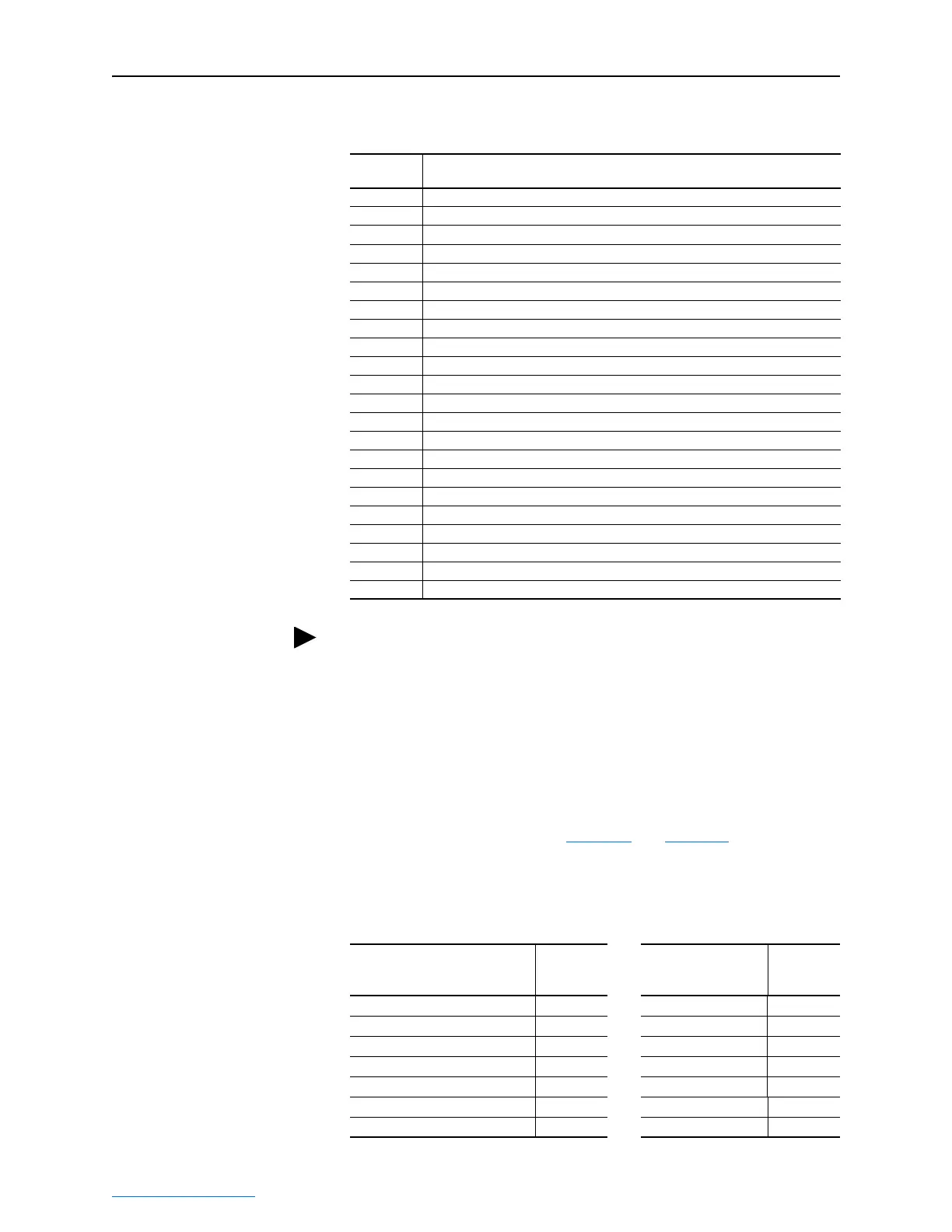
Table 5.D PLC-5, SLC 500, and MicroLogix 1100 Data Table Addresses for
PowerFlex 750-Series Drives (Continued)
Data Table
Address
Description
TIP: Remember that most of the parameters in the drive being read/
written with the Datalinks are REAL (floating point) data types.
Therefore, use a COP (Copy) instruction to convert the least significant
word and most significant word values to a single floating point register
(Fx:x).
Description
Controller
Data Table
Address
Description
Program
Data Table
Address
Drive Ready N20:1/0 Status Ready B3:1/0
Drive Active N20:1/1 Status Active B3:1/1
Actual Direction Forward (XIO) N20:1/3 Status Forward B3:1/3
Actual Direction Reverse (XIC) N20:1/3 Status Reverse B3:1/4
Drive Faulted N20:1/7 Status Faulted B3:1/7
Drive At Speed N20:1/8 Status At Speed B3:1/8
Speed Feedback N20:3 Speed Feedback B30:3

 Loading...