4-32 Configuring the I/O
PowerFlex® 755 Drive Embedded EtherNet/IP Adapter User Manual
Publication 750COM-UM001A-EN-P
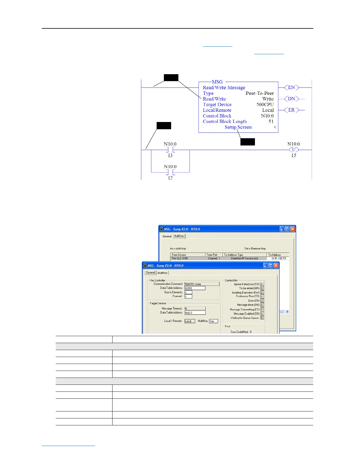
4. In the MSG instruction (Figure 4.35), double-click on Setup Screen
to launch the message configuration screen (Figure 4.36
).
Figure 4.35 SLC 500 Ladder Logic for the Control Timeout
5. Configure the General tab by entering or verifying the information
shown in the screen.
Figure 4.36 SLC 500 Message Configuration Screens for the Control
Timeout
Step 3
Step 4
Step 2
General Tab Box Setting
This Controller
Communication Command This setting is unavailable (grayed out) and is established when the message is created in the ladder rung.
Data Table Address
(1)
N20:0. An unused controller data table address containing the control timeout value to be written.
Size in Elements
(2)
1. Number of elements (words) to be transferred. Each element size is a 16-bit integer.
Channel 1. Controller port to which the EtherNet/IP network is connected.
Target Device (data for adapter/drive)
Message Timeout This setting is unavailable (grayed out). Message timeout duration in seconds.
Data Table Address
(3)
N42:3. Specific starting address of the destination file in the drive.
MultiHop Yes. Enables communication to allow Ethernet messaging to be routed to the adapter/drive. When “Yes”
is selected, a MultiHop tab appears on the message configuration screen.
MultiHop Tab Box Setting
To Addr ess 10.91.100.79. The IP address of the adapter connected to the drive.

 Loading...