English
37
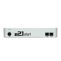
The Z21
is a ROCO and Fleischmann innovation.
• RailCom
®
is a technology developed by Lenz Elektronik GmbH for transmitting data from the decoder to the digital control centre.
Inhaltsverzeichnis
Welcome to the Z21 ....................................................................................................................................................................... 36
Technical data ................................................................................................................................................................................ 36
Included ......................................................................................................................................................................................... 36
Important information ................................................................................................................................................................... 36
1. Quick guide ................................................................................................................................................................................ 38
2. Determination of use and function ............................................................................................................................................ 39
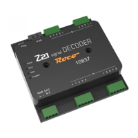
3. Installing the Z21 signal DECODER ............................................................................................................................................ 39
4. Connecting the Z21 signal DECODER ........................................................................................................................................ 40
4.1. Power supply and control centre ........................................................................................................................................ 40
4.2. Light signals ....................................................................................................................................................................... 41
4.3. Semaphore signals with magnetic drive ............................................................................................................................ 44
5. Operation on DCC control centres ............................................................................................................................................. 45
5.1. Switching commands in conventional DCCbasic format ..................................................................................................... 45
5.2. Switching commands in new DCCext format and Z21 .......................................................................................................48
5.3. Operation on control centres from other manufacturers ................................................................................................... 49
6. Conguration ............................................................................................................................................................................. 50
6.1 Conguration via the programming button ........................................................................................................................ 50
6.1.1 Option 1 – Program address ............................................................................................................................................. 50
6.1.2 Option 2 – Set number of signals ..................................................................................................................................... 51
6.1.3 Option 3 – Set addressing mode ...................................................................................................................................... 52
6.2 Conguration and rmware update via zLink .................................................................................................................... 53
6.3 Conguration via POM ....................................................................................................................................................... 54
6.3.1 Conguration via POM programming commands for accessory decoders ....................................................................... 54
6.3.2 Conguration via POM programming commands for loco decoders ............................................................................... 55
6.3.3 CV list .............................................................................................................................................................................. 56
6.4 Resetting to factory status .................................................................................................................................................. 58
7. Meaning of the LEDs .................................................................................................................................................................. 59
8. Troubleshooting ......................................................................................................................................................................... 60
Appendix A – Signal conguration “Universal” ............................................................................................................................ 61
Appendix B - Signal congurations ............................................................................................................................................... 63