Model Railway Control Unit
WWW.Z21.EU
44
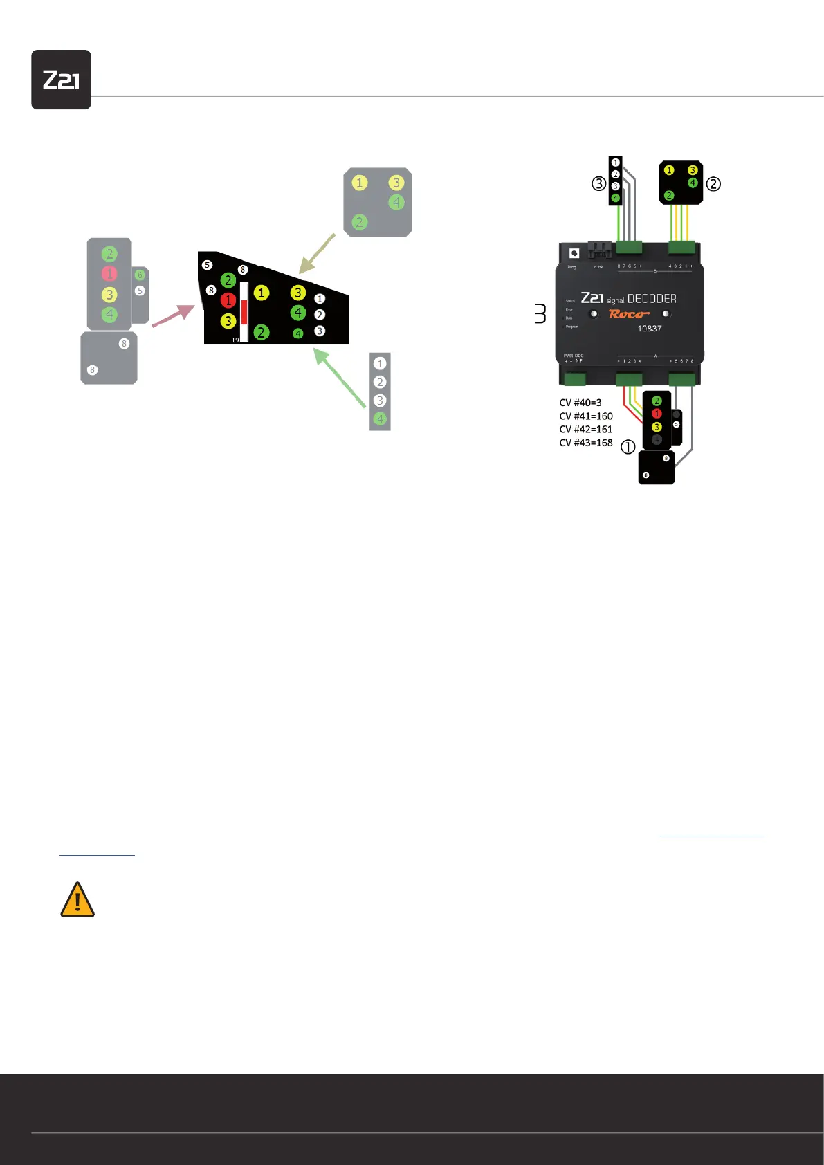
4.3. Semaphore signals with magnetic drive
Although the Z21 signal DECODER has primarily been constructed for operation with light signals, semaphore signals can also be con-
nected if they full the following conditions:
• Drives with limit switching
• Current consumption < 400 mA per drive
• Common anode
• One control line per signal aspect
For operation with semaphore signals, exclusively use those signal congurations which have expressly been designed for semaphore
signals. These are:
• Signal-ID: 162 (Hexadecimal: 0xA2) ÖBB semaphore main signal
• Signal-ID: 163 (Hexadecimal: 0xA3) ÖBB semaphore distant signal
• Signal-ID: 210 (Hexadecimal: 0xD2) DB semaphore main signal
• Signal-ID: 211 (Hexadecimal: 0xD3) DB semaphore distant signal
• Signal-ID: 213 (Hexadecimal: 0xD5) DB stop signal
In such cases, please also observe the other information stated in the individual descriptions, which you can nd in Appendix B – Signal
congurations.
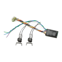
WARNING: The semaphore signals produced by Viessmann and also sold by ROCO/FLEISCHMANN with two drive cylinders
require positive control pulses (= common cathode)! To be able to connect these signals directly, one would require a control
module with a common anode, which however is no longer available.
The other semaphore signals with only one drive cylinder can be connected directly to the decoder.
Decoupled double arm semaphore signals may consume more current when switching between “Stop” and “Proceed with speed limit”
because both arms have to be moved at the same time. To avoid short-circuits, the connections for these magnetic drives are doubled
in the appropriate signal congurations.