Model Railway Control Unit
WWW.Z21.EU
58
CV Description Range Default
#211 DCC
basic
/DCC
ext
mapping for 1R, Signal 1
This CV can be used to set which signal aspect should be displayed after a DCCbasic swit-
ching command “1 Red” on signal 1.
255 = Specication in accordance with signal conguration
The DCC
basic
switching commands display the signal aspects as predened in the signal
conguration of the signal decoder selected via CV #41.
0 … 254 = Explicit specication through user
If you wish to avoid specications in the selected signal conguration, then you can enter
the DCC
ext
value here which accords with the required signal aspect. An explicit speci-
cation by the user may be expedient if, for example, the DCC system used does not yet
handle any DCC
ext
switching commands, and/or any switching sequences already available
for signals deviate substantially from those in the Z21 signal DECODER. In this case, the
Z21 signal DECODER can be adapted highly exibly to the existing system.
Example: CV #211 = 16 (“Clear to proceed”) … Signal 1 then displays, after a DCC
basic
switching command “1 Red” the signal aspect “Clear to proceed to”.
You can also nd the valid DCC
ext
value range as well as the predened assignment for the
DCC basic switching commands of your signal in Appendix A – Signal conguration “Uni-
versal” or under the link provided in Appendix B – Signal congurations.
For explanations on the DCC
basic
and DCC
ext
switching commands, see also the section
Operation on DCC control centres.
Factory setting: Specication in accordance with signal conguration
0 - 255 255
#212 DCC
basic
/DCC
ext
mapping for 1G, Signal 1
Corresponding with CV#211 for the DCC
basic
switching command “1 Green”.
0 - 255 255
#213 DCC
basic
/DCC
ext
mapping for 2R, Signal 1
Corresponding with CV#211 for the DCC
basic
switching command “2 Red”.
0 - 255 255
#214 DCC
basic
/DCC
ext
mapping for 2G, Signal 1
Corresponding with CV#211 for the DCC
basic
switching command “2 Green”.
0 - 255 255
#221
to
#224
DCC
basic
/DCC
ext
mapping for Signal 2
Corresponding with CV #211 to #214 for the signal 2.
0 - 255 255
#231
to
#234
DCC
basic
/DCC
ext
mapping for Signal 3
Corresponding with CV #211 to #214 for the signal 3.
0 - 255 255
#241
to
#244
DCC
basic
/DCC
ext
mapping for Signal 4
Corresponding with CV #211 to #214 for the signal 4.
0 - 255 255
#250 Decoder type
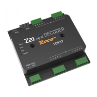
37 = ROCO 10837 Z21 signal DECODER
read only 37
6.4 Resetting to factory status
If you want to set all settings back to the original status condition, keep the programming button held down until all LEDs are lit and
the blue LED is ashing. This means that all settings are reset and the reset has been initiated.
Alternatively, the value 8 can be written back to CV#8.

 Loading...