English
45
The Z21is a ROCO and Fleischmann innovation.
5. Operation on DCC control centres
This chapter describes how the Z21 signal DECODER can be operated with the Z21 and other DCC control centres, and how to switch
a certain signal aspect.
5.1. Switching commands in conventional DCCbasic format
Model signals are still usually switched via turnout commands in the so-called DCC “Basic Accessory Command”. To simplify this rather
cumbersome name, we have abbreviated it in these instructions as “DCC
basic
” switching command. This is the switching command
which has long been used by almost all DCC control centre in order to switch a turnout to “straight” or “branch”. In connection with
signals, the command for the turnout position “straight” is also designated as “green”, and for “branch” also as “red”. However, only
two signal aspects are possible. For multi-aspect signals, multiple turnout addresses must therefore be combined.
INFORMATION: The Z21 signal DECODER reserves four consecutive turnout numbers per signal. In this way, up to 16 signal
aspects per signal are possible. If four signals are used on the Z21 signal DECODER, then the decoder even assigns 4 signals
*
4 turnout numbers =16 consecutive turnout numbers. Using the programming button on the decoder, you can set the rst
turnout number of the signal decoder, see also section Option 1 – Program address, and the process is even easier with the
Z21 per LINK.
If a signal only recognises up to max. 8 aspects, then it can be uniquely switched in the Z21 signal DECODER using only one command
(“Trigger”): the rst to fourth turnout number, either “red” or “green” results in eight possible combinations: 1R, 2R, 3R, 4R and 1G,
2G, 3G, 4G. Here the notation functions as follows:
• The numbers 1 to 4 stand for “first to fourth turnout number”, which are assigned to the signal.
• The letters “G” and “R” stand for “green” (straight) and “red” (branch).
1R is equivalent to “rst turnout number, red (branch)”, 1G is equivalent to “rst turnout number, green (straight)”, etc.
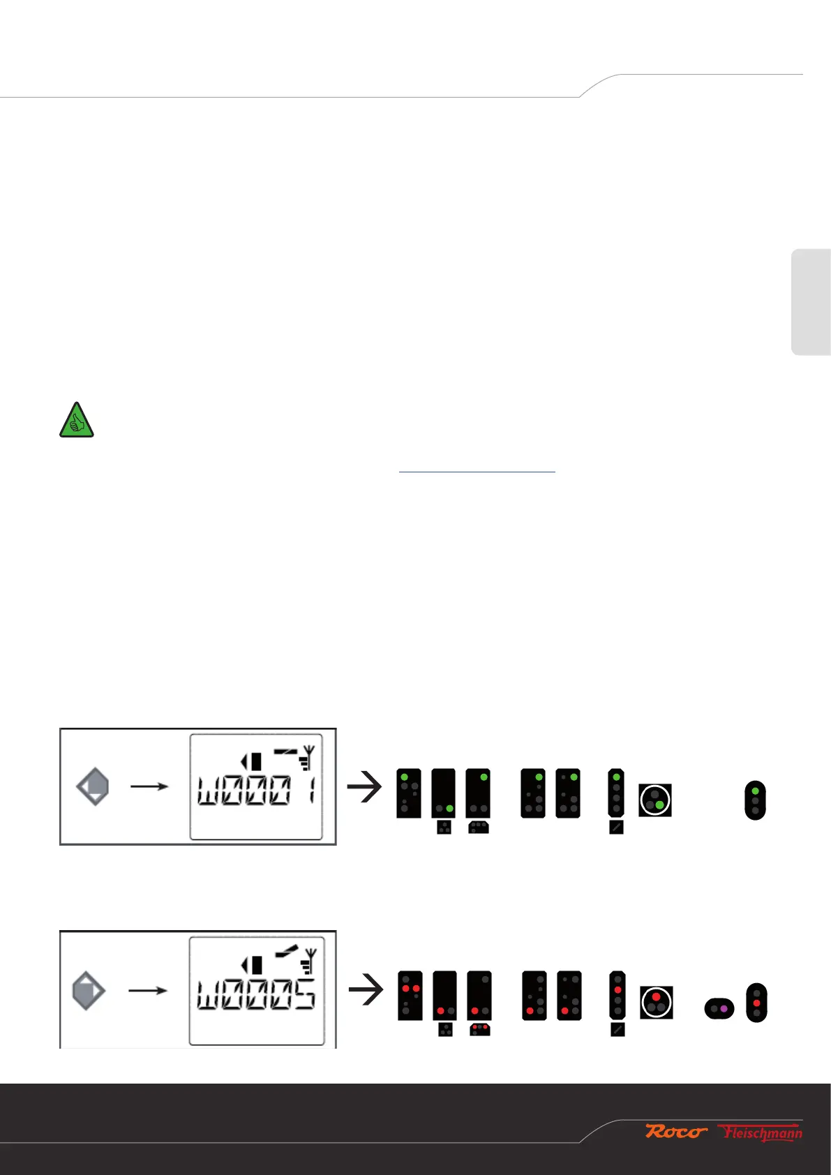
Example 1: The signal decoder is congured to address 1, and the standard signal conguration (Signal-ID=71 “Universal”) is set.
Now send the switching command 1G with the WLANMAUS or multiMAUS in order to display Clear to proceed on the rst signal.
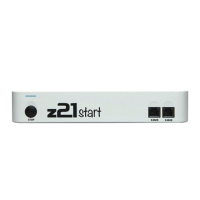
Example 2: The signal decoder is congured to address 5, and the standard signal conguration (Signal-ID=71 “Universal”) is set.
Now send the switching command 1R in order to display “Stop” on the rst signal. The rst turnout number which is assigned to the
signal is 5.