Model Railway Control Unit
WWW.Z21.EU
48
In Appendix A – Signal conguration “Universal” or under the link provided in Appendix B – Signal congurations, you will nd next
to each signal aspect the required DCC
basic
switching commands under “Trigger” and “Mode” respectively. If the “Mode” column is
empty, then this is a signal conguration which does not need a “mode”.
5.2. Switching commands in new DCCext format and Z21
Combining multiple turnout addresses for multi-aspect signals has in the meantime become common, but is not particularly conve-
nient. For this reason, all Z21 control centres (black. white) from Firmware V1.40 are able to handle DCC commands for the switching
of signals, namely the DCC “Extended accessory command” from the RCN-213 standard, simplied in this text to “DCC
ext
” switching
command. The “ext” stands for “extended”. Using this command, a value between 0 and 255 which precisely describes the required
signal aspect is sent to a unique signal address.
The benets are clear:
• It is no longer necessary to combine several different switching commands in a certain temporal sequence, but rather it is sufficient
to use one single, unique command for the required signal aspect.
• No limit of max. 16 signal aspects. There are in fact signal systems which recognise more than 16 different signal aspects: HI sys-
tem, SNCF Châssis-Écran H, ...
• Now only one single unique address is required per signal. If four signals are used on the Z21 signal DECODER, then the decoder
will only assign 4 consecutive DCCext signal addresses.
INFORMATION: The rst DCC
ext
signal address is identical in the Z21 signal DECODER with the rst DCC
basic
turnout
number (see above), and is therefore also congured in the same manner via the programming button or the Z21 per Link. The
only difference is that, although up to 16 consecutive DCCbasic turnout numbers are assigned, only max. 4 consecutive DCCext
signal addresses are assigned in the common address space.
In Appendix A – Signal conguration “Universal” or under the link provided in Appendix B – Signal congurations, you will nd next to
each signal aspect the respective appropriate value for the DCC
ext
switching command under “DCC
ext
”. The valid value range is strongly
dependent on the actual signal; common values are, for example:
• 0 ... Absolute stop aspect
• 4 ... Proceed with speed limit 40 km/h
• 6 ... Proceed with speed limit 60 km/h
• 16 ... Clear to proceed
• 65 (0x41) ... Shunting allowed
• 66 (0x42) ... Dark switching (e.g. light distant signals)
• 69 (0x45) ... Substitution signal (permits trains to pass)
The Z21 signal DECODER can interpret both DCC
basic
and DCC
ext
switching commands. This means it
need not be specially recongured. At the time these operating instructions went to print, work was
being conducted on the appropriate extension in the Z21 App, so that you can utilise this innovation
as quickly as possible, and operate your signals more conveniently. Until this feature is ready, you
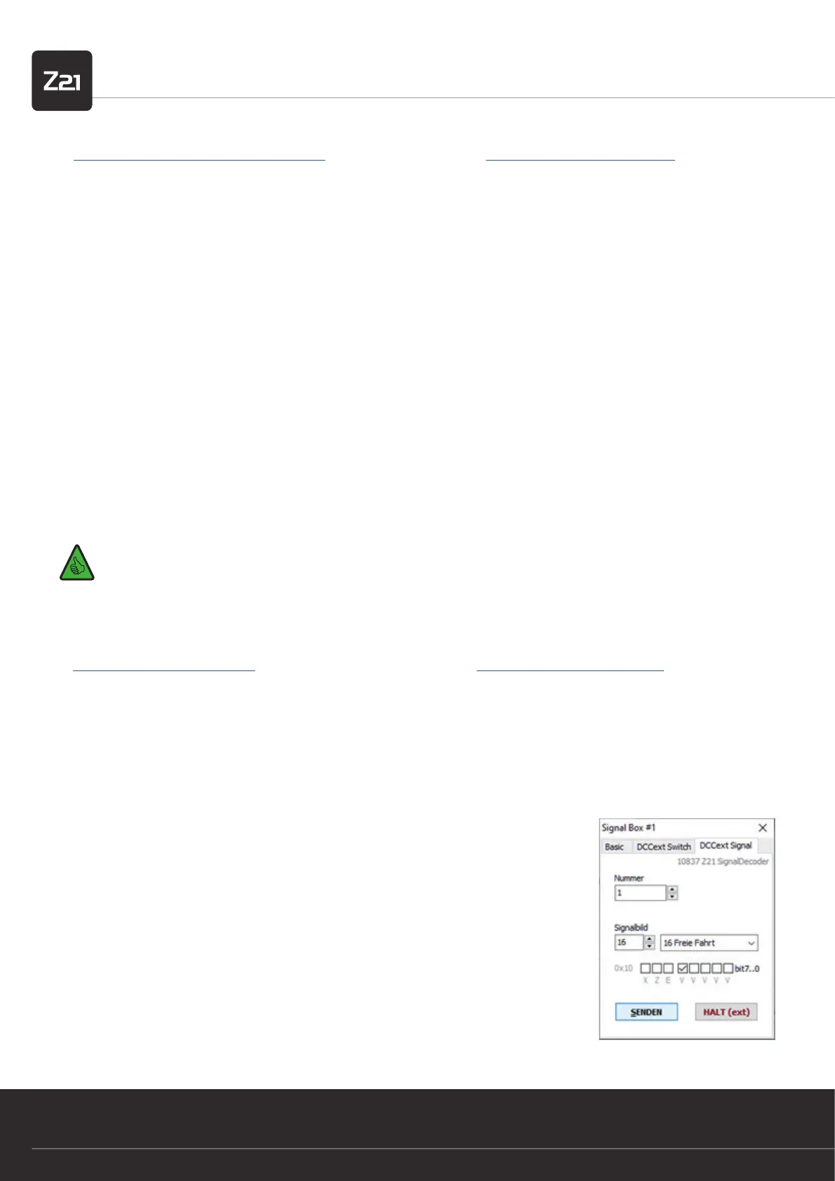
can try out the new commands in the Z21 Maintenance Tool V1.15, which can be found in the menu
Options / Signal box / DCCext signal.