Model Railway Control Unit
WWW.Z21.EU
38
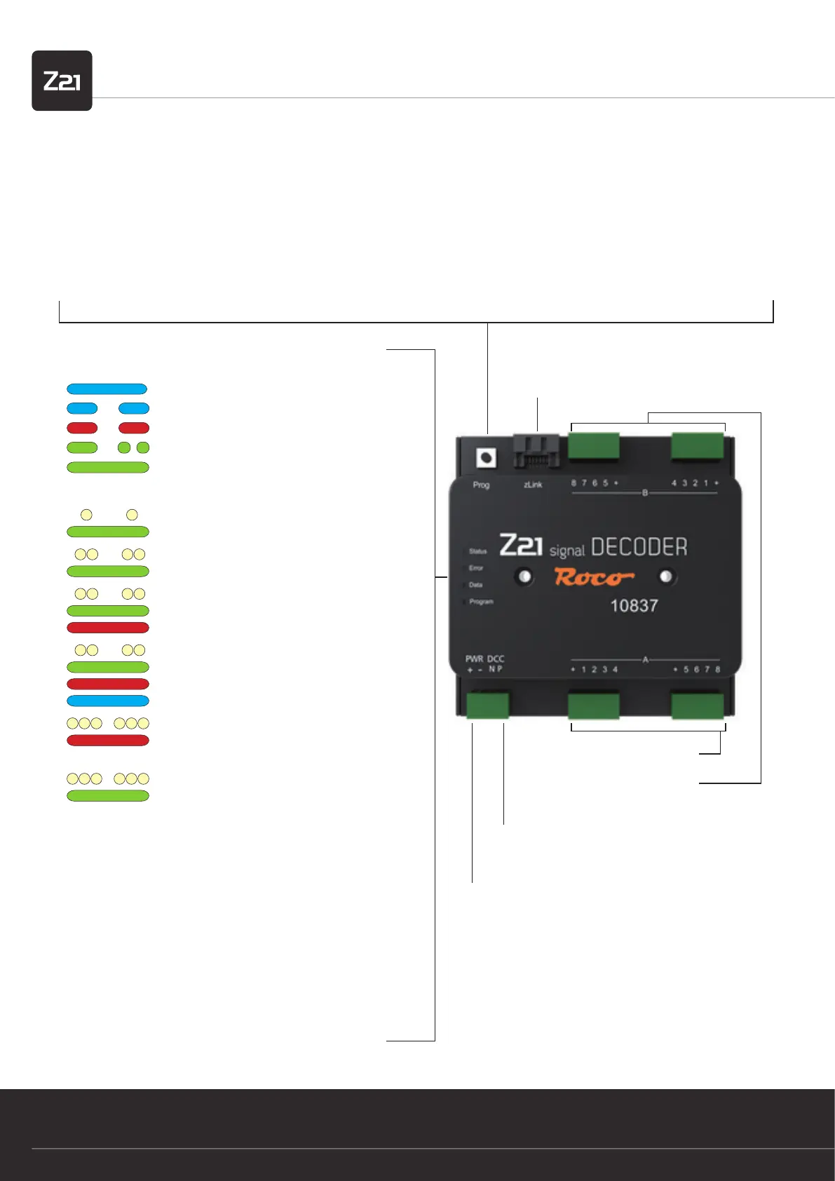
zLink
Interface for conguration and
rmware update
Programming button in normal mode:
• hold down until “Program” ashes (for at least 3 s):
Conguration mode
• hold down until all LEDs are shining (for at least 8 s):
Reset to factory settings
Programming button in conguration mode:
• press briey:
Change setting (for options 2 and 3)
• hold down until “Status” ashes blue (for at least 3 s):
next option
Signal outputs A 1 – 8
Signal outputs B 1 – 8
Congurable per signal
Track signal
DCC signal input from the control centre or booster
Supply
from track or power unit
12 – 20 V DC or DCC rail voltage
min. 2 A e.g.: ROCO 10850
Option 1:
• Switch the magnet accessory (e.g. turnout command) with the
desired address
• Address is adopted from the Z21 signal DECODER
Option 2:
The number of signals can be changed by briey pressing the pro-
gramming button.
Option 3:
The addressing mode can be changed by briey pressing the pro-
gramming button.
1. Quick guide
LEDs in normal mode
shines blue
ashes blue
ashes red
ashes green
shines green
Track signal pending
No 3 track signal
Short circuit
Data received
Addressing in conform-
ity with RCN-213
LEDs in con guration mode
ashes white once
shines green
Option 1: Set address
ashes white twice
shines green
Option 2: Number of
signals=2
ashes white twice
shines green
and red
Option 2: Number of
signals=3
ashes white twice
shines green
and red
and blue
Option 2: Number of
signals=4
ashes white 3 times
shines red
Option 3: Addressing
compatible with ROCO
or
ashes white 3 times
shines green
Option 3: Addressing
in conformity with
RCN-213