English
51
The Z21
is a ROCO and Fleischmann innovation.
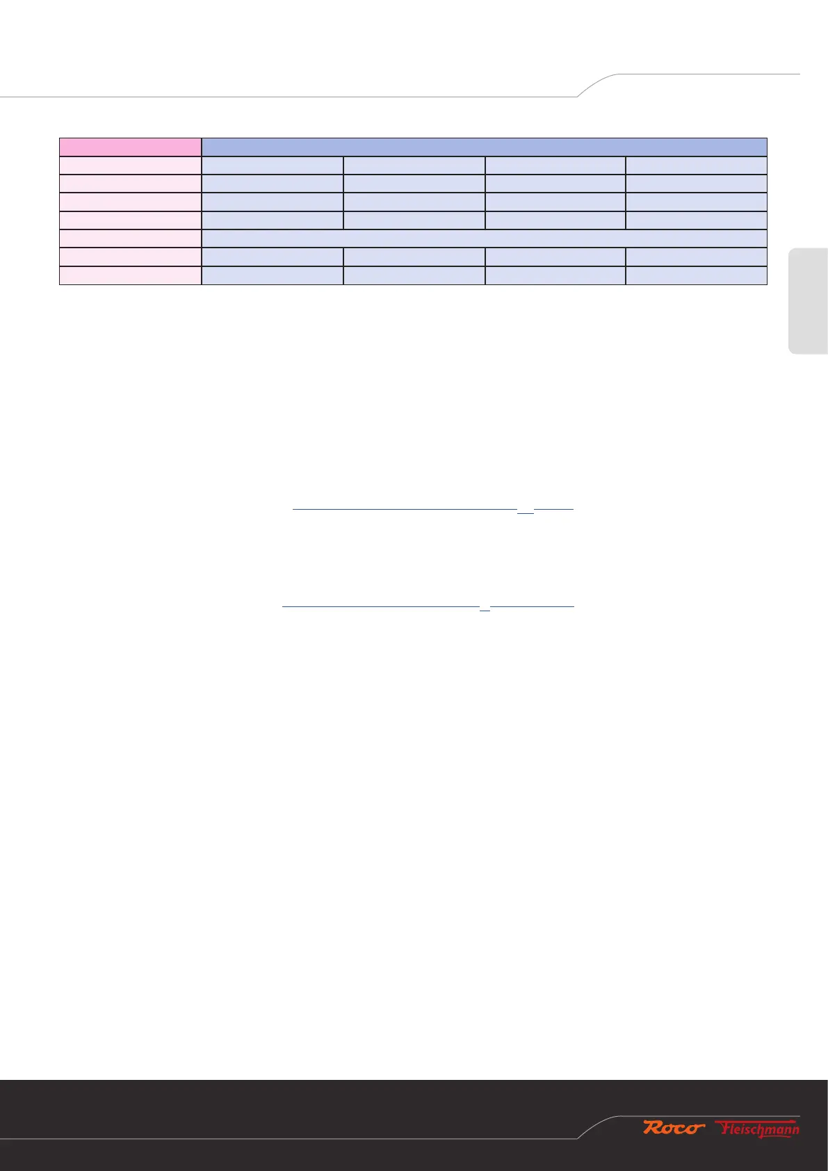
Decoder address Signals (group of four)
1 1 2 3 4
2 5 6 7 8
3 9 10 11 12
4 13 14 15 16
… …
509 2033 2034 2035 2036
510 2037 2038 2039 2040
Example 1: Switch turnout number 1 during the programming process. All signals of the signal decoder are then programmed in
ascending order to turnout numbers starting with 1.
Example 2: Switch turnout number 2 during the programming process. All signals of the signal decoder are also programmed in
ascending order to turnout numbers starting with 1, because turnout number 2 is in the same group of four as turnout number 1 from
the rst example.
Example 3: Switch turnout number 10 during the programming process. All signals of the signal decoder are then programmed in
ascending order to turnout numbers starting with 9, see the table above.
The following applies for DCC
basic
(see also Switching commands in conventional DCC
basic
format): Each signal is always numbered at
the beginning of a group of four. The beginning of the groups of four is calculated automatically when programming the signal decoder.
Each signal occupies 4 turnout numbers. If two signals are used on the signal decoder, then it occupies 2*4=8 consecutive turnout
numbers; if three signals are used, then 3*4=12 turnout numbers, and if four signals are used, 4*4=16 consecutive turnout numbers.
The following applies for DCC
ext
(see also Switching commands in the new DCC
ext
format and Z21): the rst signal is always numbered
at the beginning of a group of four. The beginning of the groups of four is calculated automatically when programming the signal
decoder. Each signal occupies just one signal address. The signal decoder therefore occupies a maximum of four consecutive DCCext
signal addresses.
The rst DCCbasic turnout number and the rst DCCext signal address are identical on the Z21 signal decoder.
Factory setting: numbered in ascending order from 1.
6.1.2 Option 2 – Set number of signals
This option is used to program the number of signals which can be connected to the signal decoder.
1. Keep the programming button held down for at least 3 seconds until the white “Program” LED begins to ash. Then release the
programming button. The white “Program” LED will then ash normally once (short, pause; short, pause; etc.), and the green
LED will be lit continuously. The signal decoder is then in “Conguration mode, Option 1”.
2. Keep the programming button held down for at least 3 seconds again until the blue “Status” LED and white “Program” LED
begin to ash together. Then release the programming button again. The white “Program” LED will then ash normally twice
(short, short, pause; short, short, pause; etc.). The signal decoder is then in “Conguration mode, Option 2”.
3. The current number of signals is then shown through the other LEDs: