EN
51
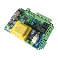
5.2 Electrical connections
A switch or an omnipolar cut-off switch with a contact opening of at least 3 mm must be
installed on the mains power line; put the cut-off switch in OFF position and disconnect any
buffer batteries before performing any cleaning or maintenance operations.
Ensure that an adequate residual current circuit breaker with a 0.03 A threshold and a
suitable overcurrent cut-out are installed upstream the electrical installation in accordance
with best practices and in compliance with applicable legislation.
For power supply, use a H07RN-F 3G1.5 type electric cable and connect it to the terminals L
(brown), N (blue), (yellow/green), located inside the control panel box.
Strip the insulation from the ends of the power cable wires which will be connected to the
terminal and secure the cable with the cable retainer.
Connections to the electrical distribution network and to any other low-voltage
conductors in the external section to the electrical panel must be on an independent
path and separate from the connections to the command and safety devices (SELV =
Safety Extra Low Voltage).
Make sure that the mains power conductors and the accessory wires (24 V) are separated.
The cables must be double insulated, strip them near the relevant connection terminals and
lock them with clamps [B] (not supplied).
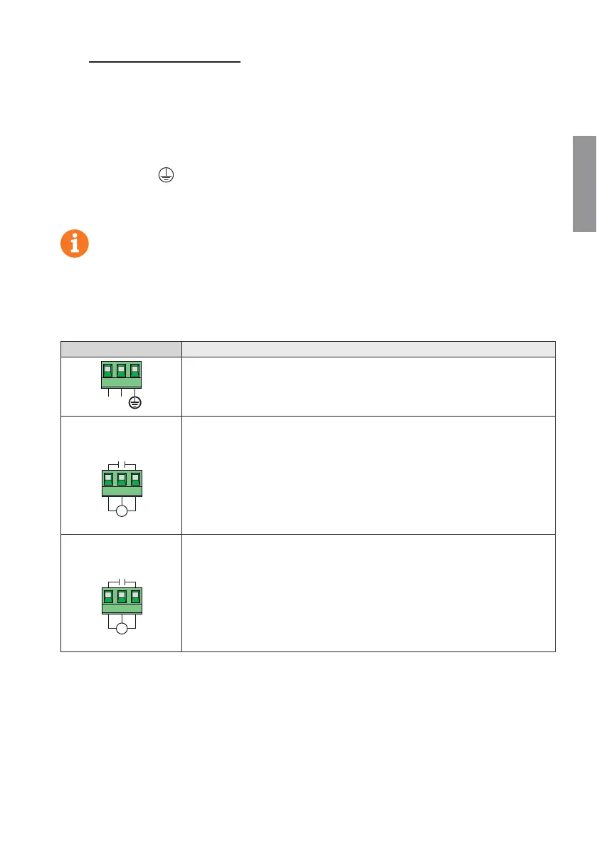
DESCRIPTION
LN
Mains power supply 230 Vac ±10% connection.
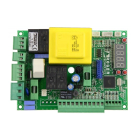
AP1-CM-CH1
M
AP1
CM
CH1
Connection to ROGER MOTOR 1.
The gate open and/or gate closed stop limit switches may be connected to the con-
trol unit. When a limit switch is activated, power is cut to the motor opening/closing
the gate.
Connect the gate open limit switch to terminals AP1-CM, and connect the gate clo-
sed limit switch to terminals CH1-CM.
To connect the limit switches directly to the control unit, refer to chapter 6.
N.B.: the value of the capacitor between AP1 and CH1 is indicated in the instructions
for the motor installed.
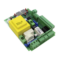
AP2-CM-CH2
M
AP2
CM
CH2
Connection to ROGER MOTOR 2.
The gate open and/or gate closed stop limit switches may be connected to the con-
trol unit. When a limit switch is activated, power is cut to the motor opening/closing
the gate.
Connect the gate open limit switch to terminals AP2-CM, and connect the gate clo-
sed limit switch to terminals CH2-CM.
To connect the limit switches directly to the control unit, refer to chapter 6.
N.B.: the value of the capacitor between AP2 and CH2 is indicated in the instructions
for the motor installed.
 Loading...