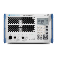
Interface Description R&S SU 4200
6.5 6125.0226.12.01
Entry in column D (direction): O = Output I = Input B = Bi-directional
Entry in column T (type): A = Analog D = Digital P = Power
Signal description D T Range Contact Remarks
*OFF I D Low (external contact
against ground)
= device off
High (or open) = on
Internal pull-up 10 k to
3.3 V, limited to max.
6.8 V
X5.7 Hardware input for
activating/deactivating
transceiver
module
+PTT I D X5.8
–PTT I D
Configurable via
software
X5.9
Pull-up resistors
connected via relay
contact to internal supply
+28 V/ –48 V
Type I:
Optocoupler inputs
+PTT and –PTT
V = 12 V to 57 V
I
source = 2 to 12 mA
Type II:
+PTT, pull-up –48 V
Contact against
Gnd = PTT
I
sink = –3 to –4 mA
R&S standard:
–PTT, pull-up +28 V,
contact against
Gnd = PTT
I
sink = 3 to 4 mA
MONITOR_TX_B O A 0 dBm ± 1.5 dB
300 to 3400 Hz
600 ±15 % balanced
X5.10 RF AM demodulation
signal derived from
antenna port
@ 85 % AM mod. depth
Audio transformer min.
500 V isolation to ground
Ethernet – LAN remote control X6\Ethernet – LAN remote control X6 «Radio».doc
+PTT
PTT
+28 V
X5
+PTT
PTT
48 V
X5
+PTT
PTT
X5

 Loading...