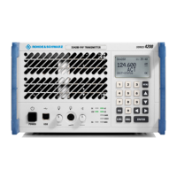
Configuring with the R&S ZS 4200 R&S SU 4200
3.11 6125.0226.12.01
PTT Input
Configuration
There are three different input configurations for the rear PTT input
(connector X5.8/9).
Type I stands for optocoupler input.
Type II should be configured if the system ground (= ground of the PTT
key) does not have the same potential as the rack ground. In this case, the
PTT circuit is fed via the negative voltage of 48 V in the radio.
With the Rohde & Schwarz standard, a pull-up resistor is switched against
the positive voltage of +28 V in the radio.
5-Carrier Offset
The transmitter allows different frequency offsets to be set. Normally the
2-carrier, 3-carrier and 4-carrier offset with the values
of 7.5 / 7.3 / 5 / 2.5 / 0 / +2.5 / +5 / +7.3 / +7.5 kHz are available. In
addition, the 5-carrier offset can be selected; this provides
8/ 4 / +4 / +8 kHz in the transmitter.
ACARS Data Mode
With this parameter the radio can be configured for voice (disabled) or
ACARS data operation (enabled) (2400 Bps).
The Voice setting is optimized for voice processing and squelch muting.
The ACARS setting is available for receiving ACARS data. In this case a
faster RF front-end control is in action. The attack and decay time is in
accordance with the ETSI EN 300676 standard.
If the radio is operating in ACARS data mode, only the 25 kHz spacing can
be used and the parameter TX Audio ALC must be deactivated.
Set/Get Values for
Preset Page
200 preset pages can be stored in the radio and called up. Each contains
the frequency and spacing parameters. These parameters can be set for
each preset page.
Installation Info
Information (up to 20 characters) can be entered to describe the radio
more precisely.
Location Info
Only the first 20 characters entered by using the R&S ZS 4200 appear on
the radio display.
IP Address
An IP address must be assigned for each radio module, which allows each
module to be uniquely identified and operated in remote operating mode.
Additionally specifying the netmask and the gateway makes it possible to
work within different subnets via a router.
ACL
(Access Control List)
Here you can enter the IP addresses of the remote control systems or
clients that are allowed to access the radio. This protects the radio against
unwanted/unknown accesses. If the list is blank (default), then any client
with any IP address can access the radio.
Note: If the SNMP protocol is used, it is necessary to add the internal IP
address 127.0.0.1 or to leave the ACL empty.
TX RS-485 Logic
Address
An address between 1 and 9999 must be assigned to each radio module.
The module is addressed on the RS-485 bus with this logical address.
RS-485 Baud Rate
The baud rate of the radio can be set. The baud rate set for the radio
(RS-485 interface) must match the baud rate of the remote control
computer.

 Loading...