4-4
1. Select PROGRAM
➻
Press
➻
2. Select SENSOR
➻
Press
➻
3. Select SENSOR
➻
Press
➻
4. Select Liquid Type
➻
Press
➻
5. Select Type
➻
Press
➻
6. Press
➻
7. Check UNITS
➻
8. Press Twice
4.4 PRIMARY DISPLAY
General. The primary display is the measurement
shown in the largest numerals. (See Figure 2-1.) The
default sensor monitored is the one at address #1.
Default units are shown in Table 4-1. The secondary dis-
play is the measurement shown in smaller numerals.
This display may be scrolled using the DISP button (F2)
to show other sensor values.
The fourth digit (rightmost) on the displayed sensor
value is for reference only. An increasing value such as
0599 may read .0500 before reading .0600 for one
cycle update. This will be corrected in later versions.
The primary display can be made to show either mea-
surement of a single sensor (Conductivity/ Temperature
or pH/Temperature), or the Difference/ Ratio between
two sensors, that are exactly the same (Type, Cell
Constant, and Units), located at address #1 and #2.
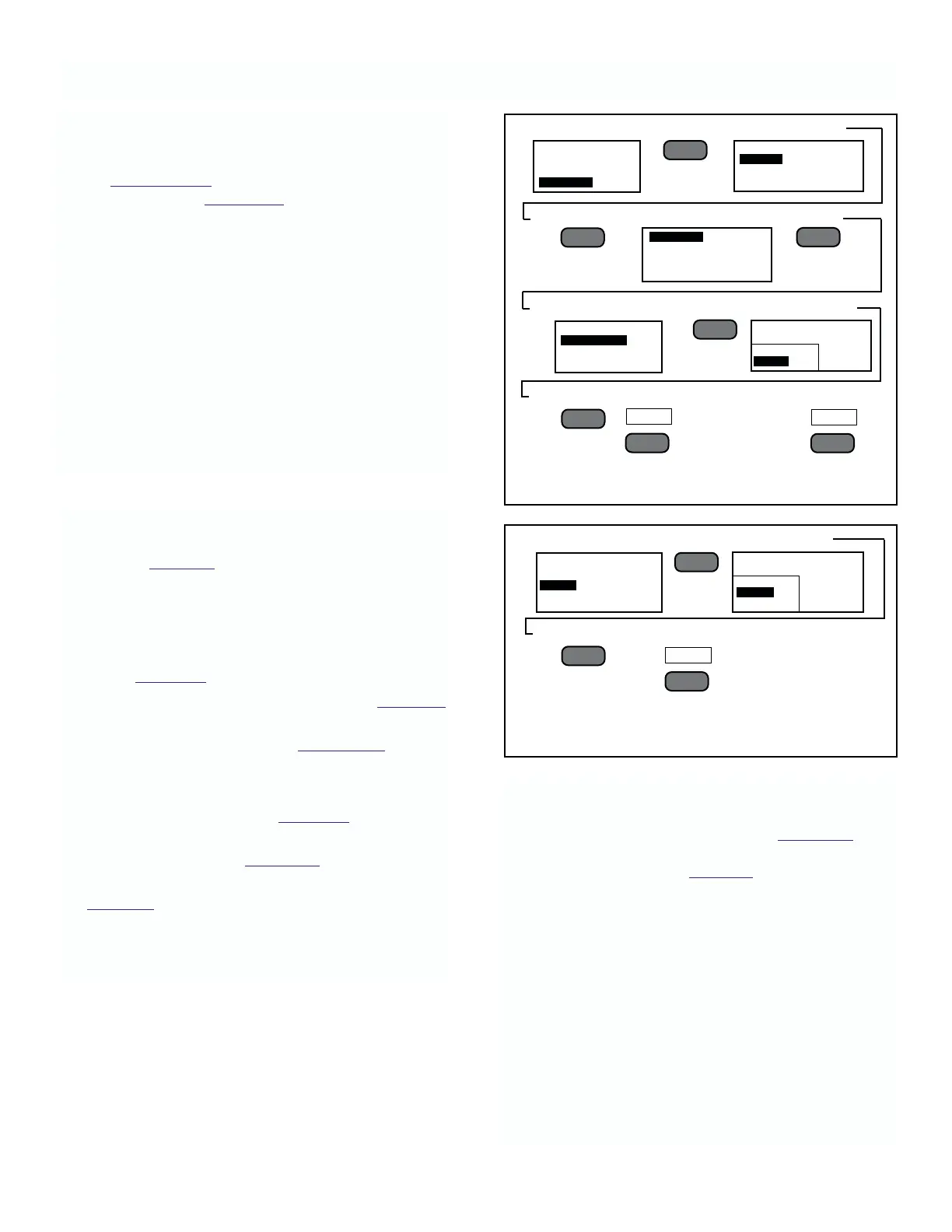
FIGURE 4-2 Changing Conductivity Liquid Type.
FIGURE 4-3. Selecting Units of Measure
or Sensors.
4. Select Units
➻
Press
➻
5. Select Scale
➻
Press
➻
6. Press Twice
4.3 SENSOR MATCHING
General. This operation is automatic and defaults are
as shown in Table 4-1. Two parameters for conductivity
sensors can be changed when necessary: Liquid Type
and Units. For pH sensors, the user must choose pH
units. The user must select mV for ORP sensors.
To Set Sensor Liquid type.
1. Follow Figure 4-1 and select the PROGRAM option.
2. Security not enabled. Follow instructions in Figure 4-2,
which gives an example for conductivity.
Security Enabled. Refer to Section 4.7 for pro-
cedure to enter Security code.
To Set Sensor Units.
1. Follow steps 1 through 4 of Figure 4-2.
2. Select UNITS instead of Liquid type, and follow
steps 4 through 6 in Figure 4-3, which shows an
example for conductivity
Table 4-2 lists the units available for each type of
conductivity sensor. For pH/ORP sensors, the
available units are pH or mV (ORP).
MODEL 2700 SECTION 4.0
CONFIGURATION
––
l
▲
––
l
▲
PROGRAM
SENSOR
PRIMARY DISPLAY
INSTRUMENT ADDRESS
PREV
F2
MAIN MENU
ALARMS
OUTPUT
PROGRAM
SENSOR X
LIQUID TYPE
UNITS
––
l
▲
SENSOR 1 PROGRAM
SENSOR 2
SENSOR 3
SENSOR 4
––
l
▲
––
l
▲
EXIT
F4
LIQUID TYPE-SENSOR X
AVAILABLE CURRENT
PURE WATER
WATER
MENU
––
l
▲
F1
SENSOR 1 PROGRAM
LIQUID TYPE
UNITS
SENSOR X
AVAILABLE COND
mS/cm
mS/cm
Kohm_cm
––
l
▲
NOTE
If the SECURITY Code has been changed
from 0000, a request for security code
(Figure 4-16) will appear. Follow
instructions in Figure 4-16.
Hold Function. Whenever this analyzer is placed into
the Menu mode, the present current output is held until
the analyzer is returned to the Process mode.
When returned to the Process mode the analyzer
generates a new output based on the new parameters.
WARNING:
The change will take place immediately
upon return to the Process mode! Be sure
the new parameters will not cause an
excessive upset to the process.