4-6
1. Select Alarm
➻
Press
➻
2. Select Alarm 1
➻
Press
➻
3. Select Sensor
➻
4. Press to move
➻
5. Press to save &
w/ scrolling keys on w/o saving move to next field.
➻
6. Set value with
➻
Press
➻
Repeat step 6 until
scrolling keys Alarm & Deadband
points are to spec.
➻
Press
➻
10 Press Twice.
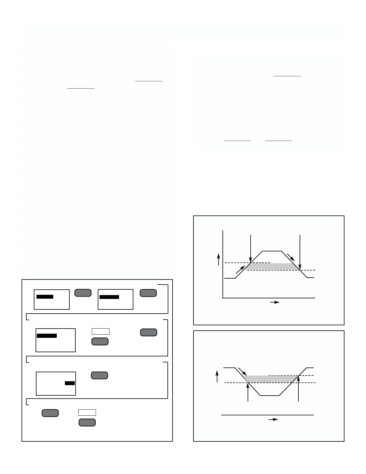
Process level
Normal
Level
Setpoint
Dead Band Pt.
Alarm Activated
Alarm Deactivated
Time
FIGURE 4-7. High Level Alarm
DEADBAND
Process level
Normal
Level
Setpoint
Alarm Activated Alarm Deactivated
Time
Dead Band Pt.
DEADBAND
MODEL 2700 SECTION 4.0
CONFIGURATION
4.5 ALARMS
General. There are two process and one error output
relay. The process alarm relays each have their own
adjustable setpoint and deadband point that may be
used to set up either a High level alarm (Figure 4-7) or
Low level alarm (Figure 4-8).
The error relay closes when an error is sensed. This
relay will stay closed until the function key F3 is pressed
and the error display is exited to the process display.
The two process relays may be set from the keypad to
either “NO” (Normall Open, Failsafe), “NC” (Normally
Closed, Non-Failsafe). The operation of these settings
are described further as follows (with “Normal” being
defined as the condition when the unit is powered up
and in operation, and not in alarm):
Menu Selection Set to “NO”
• In Normal Condition, relay is open
• If power is lost while in Normal Condition, relay closes
• In Alarm Condition, relay closes
• If power is lost while in Alarm Condition, nothing
happens (relay stays closed)
Menu Selection Set to “NC”
• In Normal Condition, relay is closed
• If power is lost while in Normal Condition, nothing
happens (relay stays closed)
• In Alarm Conditions, relay opens
• If power is lost while in Alarm Condition, relay closes
To Set Alarm Setpoint, Deadband Point, and
Contacts.
1. Follow directions given in Figure 4-6.
Each monitors the process with its’ own setpoint,
deadband point, and contact operation.
When the monitored measurement reaches the setpoint,
the alarm activates. The deadband point is that value at
which the alarm deactivates.
Set the deadband point below the alarm setpoint for a
High alarm; the deadband above the setpoint for a Low
alarm. See Figure 4-7 and Figure 4-8 for examples.
FIGURE 4-6. Setting Alarm and Deadband Setpoints
––
l
▲
––
l
▲
ALARM SETUP
ALARM 1
ALARM 2
––
l
▲
NEXT
F3
––
l
▲
––
l
▲
EXIT
F4
MAIN MENU
ALARMS
OUTPUT
PROGRAM
ALARM 1
SENSOR 1 mS/cm
ALARM PT: 10.00
DEAD BAND PT: 9:00
CONTACTS NO
ALARM 1
SENSOR 1 mS/cm
ALARM PT: 10.00
DEAD BAND PT: 9:00
CONTACTS NO
FIGURE 4-8. Low Level Alarm