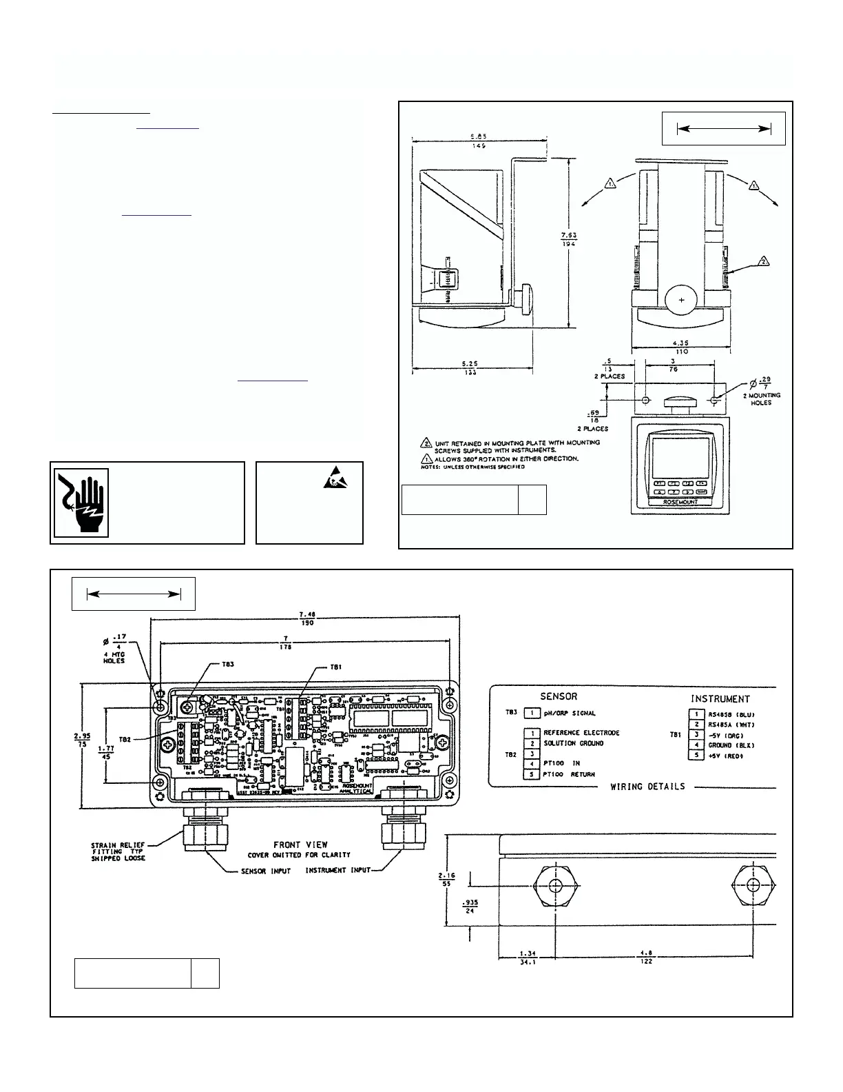
FIGURE 1-4B. pH/ORP Preamp J-Box P/N 23054-03.
1-3
MODEL 2700 SECTION 1.0
INSTALLATION AND QUICK START-UP
Wall Mounting. Requires wall mounting kit, Model
WMB-5. See Figure 1-4 for installation diagram.
1. With rear cover installed, remove at least two
knockouts for wire entry. One for sensor wires,
the second for all others.
3. Install water tight conduit connectors called
out in Figure 1-1. Rosemount offers these
connectors in kit number 23596-00.
When rigid conduit is to be used, install fittings
on the conduit first to prevent damage to the
instrument case.
4. Mount bracket to wall.
5. Insert analyzer into cutout provided on wall
mounting bracket. Insert both mounting
brackets. Tighten screws to lock in place.
6. After wiring according to Section 1.3, replace
rear cover, position assembly, and tighten jam
knob on top.
▲▲
! WARNING
▲▲
!
MAIN POWER AND RELAY CON-
TACTS WIRED TO SEPARATE
POWER SOURCE MUST BE DIS-
CONNECTED BEFORE SERVICING.
ATTENTION
INSTRUMENT CONTAINS
ELECTROSTATIC SENSITIVE
DEVICES
.
OBSERVE PRE-
CAUTIONS FOR HANDLING
FIGURE 1-4. Wall Mounting Assembly WMB-5.
DWG. NO. REV.
40270003 A
DWG. NO. REV.
40270001 A
MILLIMETER
INCH
MILLIMETER
INCH