6-1
MODEL 2700 SECTION 6.0
TROUBLESHOOTING
SECTION 6.0
TROUBLESHOOTING
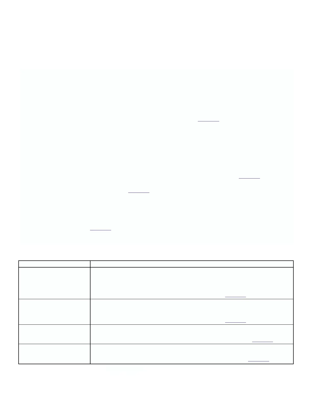
Diagnostic Message Description and Suggested Actions
Instrument Faults
SENSOR DRIVER ERROR
Analyzer recognizes a malfunction in the sensor RS485 serial communication circuit.
• Toggle power.
• Replace sensor.
• Replace Electronics Module. See Replacement Parts in Table 5-1.
STD RS485 DRIVER ERROR Analyzer recognizes a malfunction in the user RS485 serial port circuit.
• Remove RS485 cable or wiring.
• Toggle power; if error does not return, check cable wiring
• Replace Electronics Module. See Replacement Parts in Table 5-1.
EEPROM ERROR Analyzer recognizes an instrument EEPROM failure.
• Toggle power.
•
If error persists, replace Electronics Module. See Replacement Parts in
Table 5-1
.
DISPLAY ERROR Analyzer recognizes a malfunction with the display circuit.
• Toggle power.
• If error persists, replace display board. See Replacement Parts in Table 5-1.
(Cont next Page)
6.1 OVERVIEW
The Solu Cube 2700 Analyzer automatically performs self-diagnostics during normal operation. These diagnostic tests
cover most of the problems likely to be encountered.
At the same time, calculations are made from the sensor input and monitored for conditions that would indicate an
incorrect measurement. RTD values are monitored for errors that would indicate an RTD open or shorted. Electrodes are
monitored for shorted or open conditions.
When an error condition does exist, the ERR field on the Process display will start flashing. Press the F3 keypad directly
under the ERR annunciation field to display information about the error. See T
able 6-1 for a listing of these diagnostic
messages, descriptions of possible causes, and some possible actions to take to clear the ERR message.
In addition, the Error relay is closed when this field is activated. This relay can be used as a sensing device for external
annunciation of the Error message. The error message is also available from the serial port.
Since this instrument is not an analog device, previous setups that simulated conductivity sensors no longer work.
Instead, a “known good” sensor, or solution, must be used to determine if the trouble exists in the sensor or the analyzer.
Exchanging positions of like sensors to see if the problem follows one or the other sensor will also be useful.
Troubleshooting.
1. Look for a diagnostic fault message, on the display, to help pinpoint the problem. Refer to T
able 6-1 for a listing of
the messages and possible problems that may have triggered them.
2. Refer to the Quick Troubleshooting Guide, Table 6-2, for common loop problems and the recommended actions to
resolve them.
6.2 DIAGNOSTIC MESSAGES
The Model 2700 Solu Cube Analyzer software diagnostics constantly monitor the input loop for possible problems.
When the ERR field flashes, press F3, to display error message. These error messages will replace the Process display.
Note the message and refer to T
able 6-1 for a description of problems that may have triggered the diagnostic message.
All Sensor and Analyzer error messages are available through the serial I/O port.
TABLE 6-1. Diagnostic Fault Messages