1-4
1.3 ELECTRICAL INSTALLATION
General. Keep sensor and power wires separated with-
in the case as much as possible.
All wiring connected to this analyzer must be rated at
least 240 Volts. AC power wiring should be 14 gauge or
greater.
The user must provide a means to disconnect the main
power supply in the form of a circuit breaker or switch.
The circuit breaker or switch must be located in close
proximity to the instrument and be identified as the
diconnecting device for the instrument.
Figure 1-5 identifies terminal block connections for input
power, output current or voltage, sensor inputs, alarm
relays, and non-isolated RS485 output. Optional output
connections are shown below.
MODEL 2700 SECTION 1.0
INSTALLATION AND QUICK START-UP
WARNING
Make sure power to instrument is OFF before
attempting to connect any wires inside of rear
opening.
NOTICE
Do not place sensor wiring in the same conduit
as power wiring.
Strain reliefs do not provide grounding between
conduit connections and analyzer case. Use
grounding type bushings and jumper wires.
For maximum EMI/RFI protection the output
cable(s) should be shielded and enclosed in an
earth grounded rigid metal conduit. Connect the
cable’s outer shield to the instrument’s earth
ground via terminal 4 of TB1, Figure 1-5.
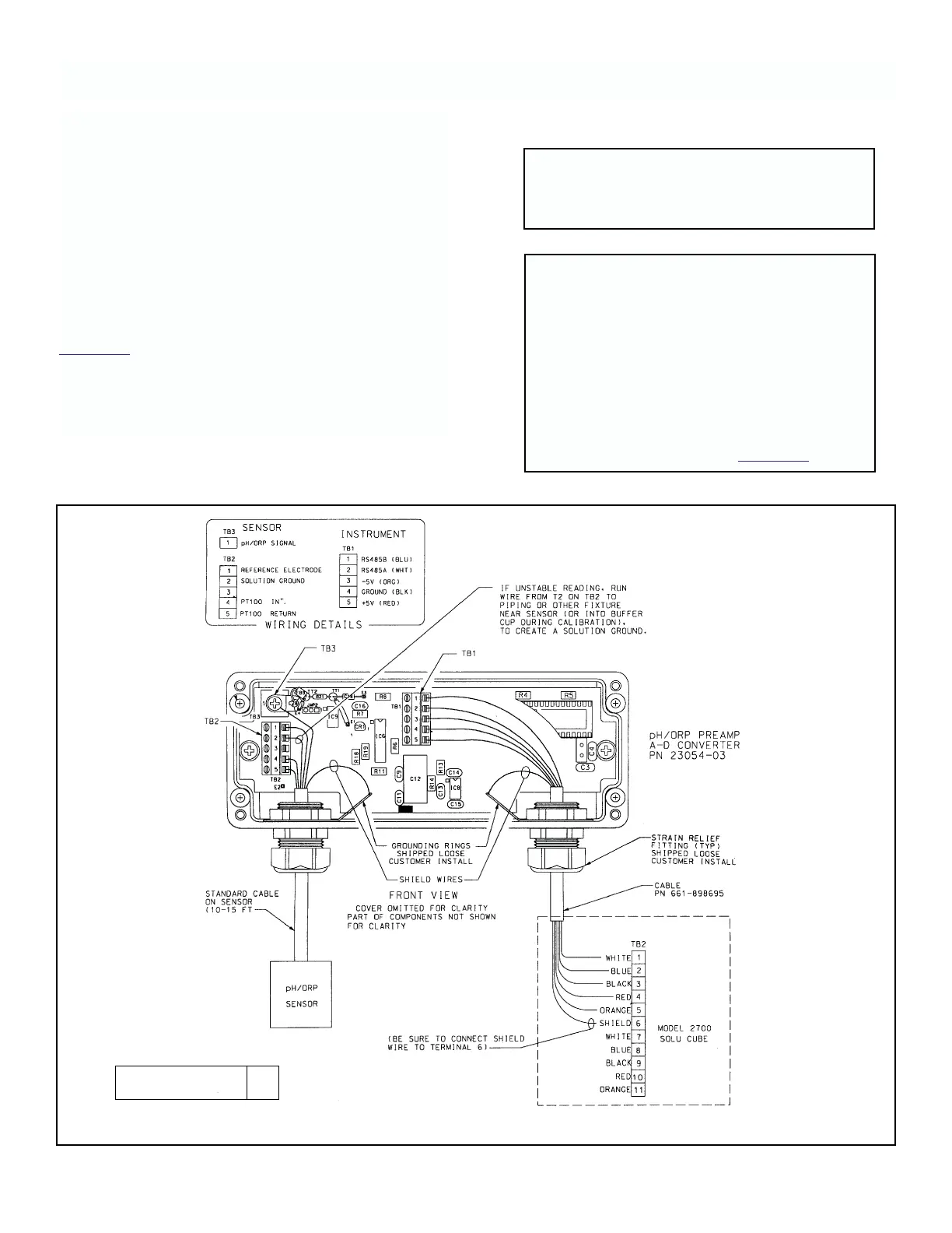
FIGURE 1-4C. pH/ORP Sensor Wiring.
DWG. NO. REV.
40270015 A