4-10
From
➻
1. Press
➻
2. Select View
➻
3. Select Version
➻
4. Press
➻
➻
See
➻
6. End with
➻
➻➻➻
➻➻
12. If incorrect
➻
13. If correct
MODEL 2700 SECTION 4.0
CONFIGURATION
F1
MENU
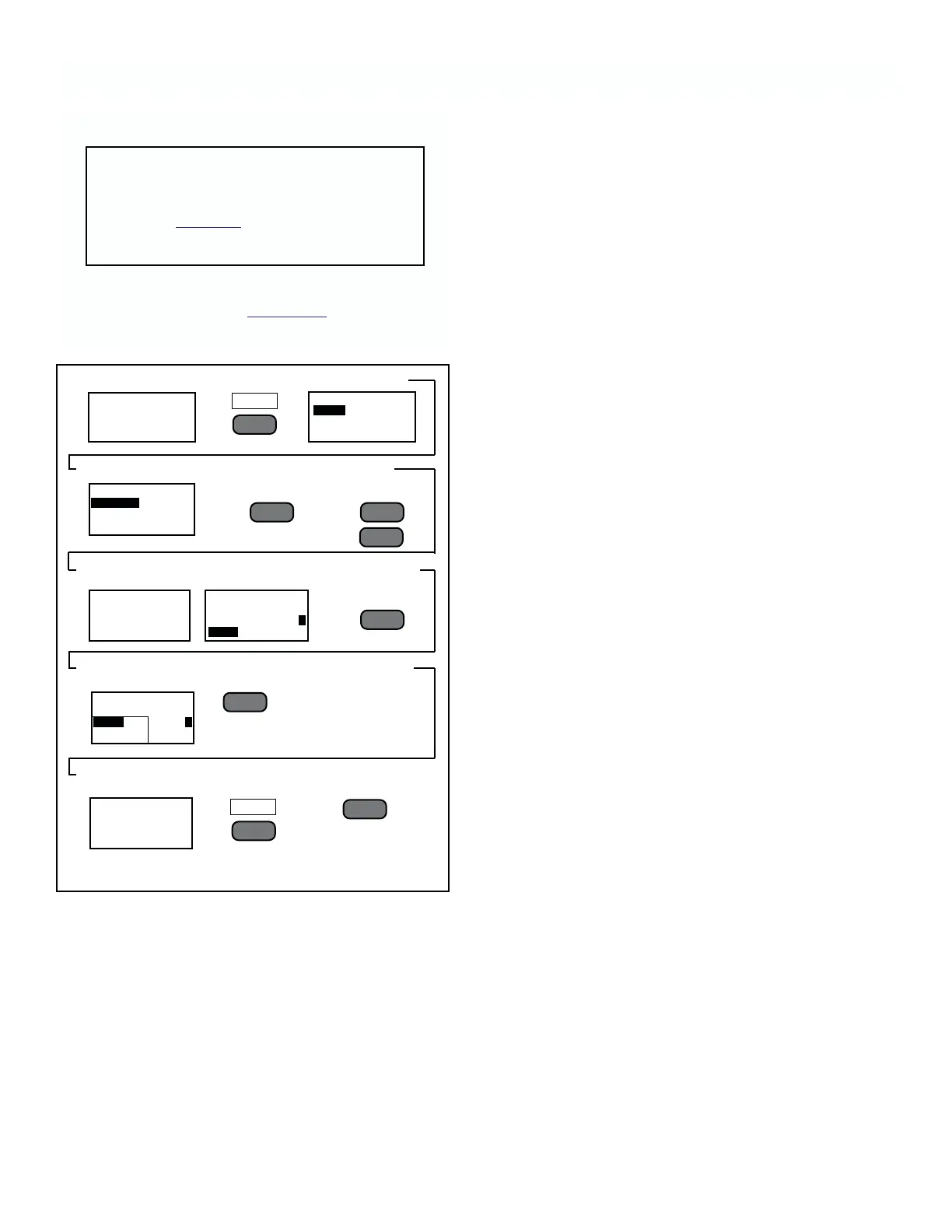
FIGURE 4-18. Changing Sensor Address.
.3051
RATIO
1.324 µS.cm
SENSOR 1
MAIN MENU
VIEW
CALIBRATE
ALARMS
VIEW
VERSION
SENSORS
ALARM 1
################
################
################
################
4.9 SENSOR ADDRESSING
CAUTION
The following procedure returns all para-
meters to their default values. Check or
complete Table 4-1 before starting the fol-
lowing steps.
To change the address assigned to individual sensors
follow the steps outlined in Figur
e 4-18.
AVAILABLE PRESS
(<––
l
)
S/N TO ASSIGN
00123 ADDR: 1
00124
AVAILABLE PRESS
(<––
l
)
S/N TO ASSIGN
00123 ADDR: 2
REVIEW ADDR LIST
ADDR S/N TYPE
1 00123 K.01
2 00124 K.01
––
l
▲
––
l
▲
––
l
▲
REDO
F2
F1
F3
––
l
▲
5. Press
simultaneously
and release
7. Select sensor
to be at address
#1 and
10. Repeat steps
7 & 8 for all sensors
on input loop
8. Select
sensor #2
11. Check
Addresses
9. Press