1-2
MODEL 2700 SECTION 1.0
INSTALLATION AND QUICK START-UP
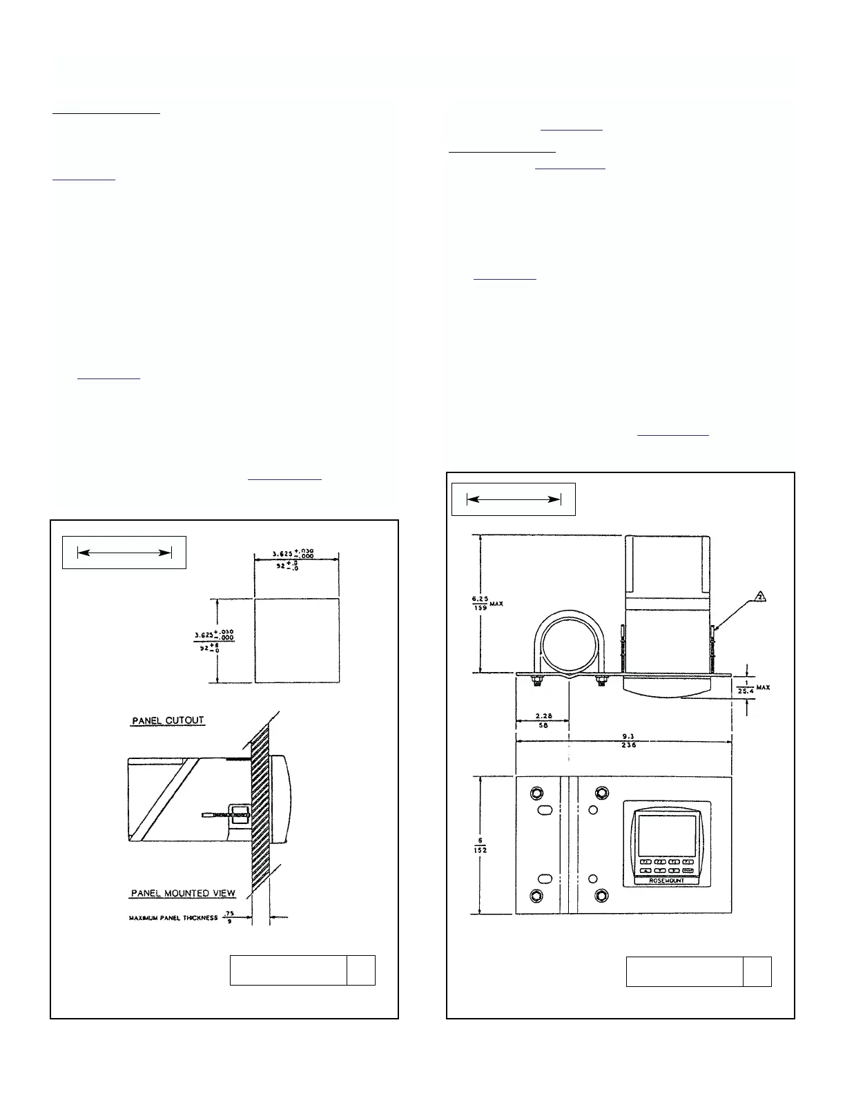
FIGURE 1-2. Panel Mounting FIGURE 1-3. Pipe Mounting Assembly - PMB-5
Panel Mounting. The analyzer is designed to fit into a
1/4 DIN, panel cutout 92 x 92mm (3.625 x 3.625 inch)
maximum depth of 178mm (7 inches) per DIN 43 700.
Panel thickness up to 19mm (.750 Inches) thick. See
Figure 1-2.
Installation requires both front and rear access. If
access from the rear of the control panel is difficult, the
instrument can be wired before installation into cutout.
Rear cover and mounting brackets cannot be
assembled to case until wiring is complete and unit has
been inserted into cutout. To install:
1. With rear cover installed, remove at least two
knockouts for wire entry. One for sensor wires, the
second for all others.
2. Install watertight conduit connectors called out in
Figure 1-1. Rosemount offers these connectors in kit
number 23596-00.
When rigid conduit is to be used, install fittings on
the conduit first to prevent damage to the instru-
ment case.
3. After wiring according to Section 1.3, insert rear
cover and case into panel opening.
4. From rear, attach rear cover and mounting brackets
as seen in Figure 1-1.
Pipe Mounting. Requires pipe mounting kit, Model
PMB-5. See Figure 1-3 for installation diagram. To
install:
1. With rear cover installed, remove at least two
knockouts for wire entry. One for sensor wires, the
second for all others.
2. Install watertight conduit connectors called out in
Figure 1-1. Rosemount offers these connectors in kit
number 23596-00.
When rigid conduit is to be used, install fittings on
the conduit first to prevent damage to the instru-
ment case.
3. Make sure there is sufficient room to access rear
cover and terminal blocks inside case, or to pivot
mounting plate to allow access.
4. After wiring according to Section 1.3, replace rear
cover and position assembly. Tighten U-bolt nuts.
DWG. NO. REV.
40270002 A
DWG. NO. REV.
40270004 A
MILLIMETER
INCH
MILLIMETER
INCH