Instruction Manual
IM-106-350C, Rev 2.2
July 2008
D-11
Hazardous Area Oxymitter 5000
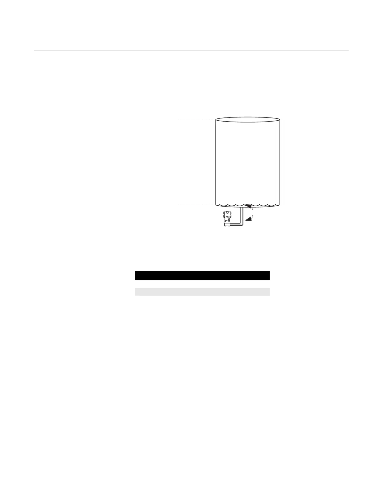
Situation #2
The transmitter in situation #1 is installed below the tank in a position where
the liquid column in the impulse line, when the tank is empty, is equivalent to
2.0 psi (Figure D-6).
Figure D-6. Situation #2
Diagram
Solution
Table D-5 lists the appropriate configuration settings.
Table D-5. Analog Input
Function Diagram for a Pressure
Transmitter used in Level
Measurement (Situation #2)
38740088
16ft
0ft
2.0psimeasuredat
thetransmitter
Empty Tank
Parameter Configured Values
L_TYPE Indirect
XD_SCALE 2 to 9 psi
OUT_SCALE 0 to 16 ft
 Loading...


