12 IQ3 manual – Section: Preparing the Drive Bush
5. Preparing the Drive Bush
5.1 IQ base all sizes types A and Z3
Turn actuator onto its side, remove the
cap-headed screws holding retaining
plate (1) onto the thrust base and pull
out the drive bush (2) complete with its
bearing assembly (3). Size IQ10 to 35
have 2 screws, size IQ40 to 95—F25
bases have 8 screws, and F30 have 10
screws. Before machining the drive bush
the thrust bearing must be removed.
IQ10 to 18 actuators have a sealed
thrust bearing located on the drive
bush and retained by the split collar (4)
and snap ring (5).
IQ20 to 95 have a thrust race bearing
within a steel bearing housing located
on the drive bush and retained by the
split collar (4) and snap ring (5). The
bearing is sealed within its housing by
O-rings located on the drive bush and
the bearing spacer ring (6).
WARNING: Failure to remove
the bearing assembly and O-rings
from the drive bush prior to
machining may result in damage
to the bearing.
Disassembly of bearing assembly
all sizes
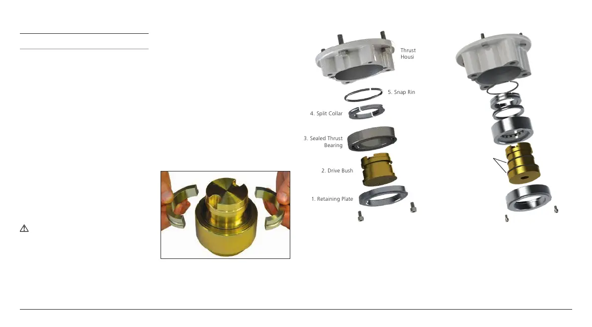
Locate and remove the snap ring (5)
using a suitable tool. Remove the
split collar (4) See Fig. 5.1.1. Slide the
bearing (3) off the drive bush (2).
Note Additional spacer (6) and O-rings
to remove on sizes IQ20 to 95.
Keep the bearings and drive bush
locating components in a safe clean
place. The split collar (4) must be kept
as a matched pair.
Machine the drive bush (2) to suit
the valve stem, allowing a generous
clearance on the screw thread for rising
steam threads.
Fig. 5.1.1
1. Retaining Plate
2. Drive Bush
3. Sealed Thrust
Bearing
5. Snap Ring
4. Split Collar
Thrust Base
Housing
Fig. 5.1.2 F10 base assembly
1. Retaining Plate
2. Drive Bush
O-rings
3. Thrust Bearing
4. Split Collar
6. Bearing Spacer
Ring
5. Snap Ring
Thrust Base
Housing
Fig. 5.1.3 F14 & F16 base assembly

 Loading...