IQ3 manual – Section: Commissioning - Basic Settings 21
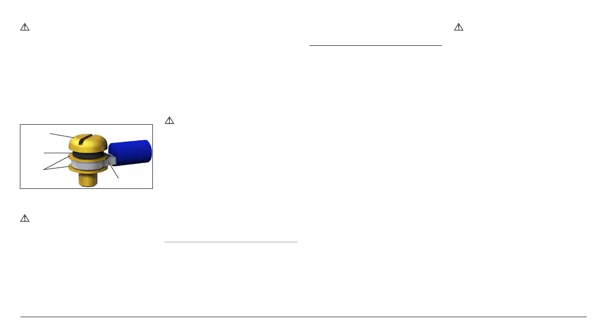
To ensure secure electrical
connections, it is important
that the requisite washers are
used as shown in Figure 7.5.1.
Failure to do so may result in
connections working loose or
screws not clamping down on
wire termination tags. Spring
washers must be compressed.
Screw tightening torques must not
exceed 1.5 Nm (1.1 lbf.ft)
4 or 5 mm
Pan Head
Spring
washer
Plain
washers
Wire tag
Fig. 7.5.1
To comply with Ex e certification,
terminals numbered 1 - 3 and earth
must be fitted with 1 off AMP
ring tag 160292 per terminal and
terminals numbered 4 - 47 must be
fitted with 1 off AMP ring tag 34148
per terminal when required.
Refer to the wiring diagram inside the
terminal cover to identify functions of
terminals. Check the supply voltage
is the same as that marked on the
actuator nameplate.
Remove power terminal guard.
Begin by connecting power cables and
replace guard. When all connections
are made ensure wiring diagram is
replaced in the terminal compartment.
WARNING: Wiring can reach
80
o
C in a 70
o
C ambient
temperature. For safety reasons
the same voltage level must be
connected to all the actuator's
indication terminals, remote input
terminals and digital I/O terminals
(if applicable).
All external circuits must be provided
with insulation suitable for the rated
voltage whilst considering national
regulations and statutory provisions.
7.6 Replacing Terminal Cover
Ensure cover O-ring seal and spigot
joint are in good condition and lightly
greased before refitting cover.
8. Commissioning - Basic
Settings
All actuator settings, Datalogger and
asset management data is accessed
using the supplied Rotork Bluetooth
®
Setting Tool Pro. Status and alarm data
in addition to that shown on the home
screen can also be accessed.
THE CONTROL COVER MUST
NOT BE REMOVED; NO USER
CONFIGURABLE SETTINGS ARE
AVAILABLE WITHIN THE CONTROL
ENCLOSURE. THE CONTROL
COVER IS SEALED BY A QUALITY
LABEL WHICH IF BROKEN MAY
INVALIDATE WARRANTY.
This instruction details the basic
settings that must be completed before
the actuator is put into service.
ELECTRICAL OPERATION MUST
NOT TAKE PLACE UNTIL THE BASIC
SETTINGS HAVE BEEN MADE AND
CHECKED.
The basic settings affect the correct
operation of the valve by the actuator.
If the actuator has been supplied with
the valve, the valvemaker or supplier
may have already made these settings.
Settings and operation must be
verified by electric operation and
function test of the actuated valve.
THIS PUBLICATION PROVIDES
INSTRUCTION ON MAKING THE
BASIC SETTINGS ONLY.
For instruction on control and
indication settings and for information
on diagnostics refer to PUB002-040.

 Loading...