IQ3 manual – Section: Preparing the Drive Bush 13
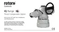
O-rings
4. Split Collar
6. Bearing Spacer
Ring
1. Retaining Plate
2. Drive Bush
3. Thrust Bearing
5. Snap Ring
Thrust Base
Housing
Fig. 5.1.4 F25 & F30 base assembly
Reassembly
WARNING: Failure to fully clean
and grease the drive bush and
O-rings before reassembly could
result in damage.
Remove all swarf from the drive bush
(2) ensuring all O-rings are undamaged,
clean and greased (for typical greases
refer to Section 11, weights and
measures).
Slide the bearing assembly (3) onto the
drive bush (2) and ensure it is fitted
down to the drive bush shoulder. On
size IQ20 to IQ95 refit bearing spacer
ring (6) into bearing assembly ensuring
O-ring is fitted and greased. Grease
and refit matched pair split collar (4)
and snap ring (5).
Grease and refit the drive bush bearing
assembly into the thrust base housing
on the actuator, ensuring that the slots
in the drive bush are located into the
drive dogs of the hollow output shaft.
Refit the retaining plate (1) and secure
with cap headed screws. For IQ40 to
IQ95 tighten base retaining screws to
the following torque values:
F25 / FA25 Base — 8 off / M12 cap
head screws: 89 Nm / 65 lbs.ft
F30 / FA30 Base — 10 off / M16 cap
head screws: 218 Nm / 160 lbs.ft
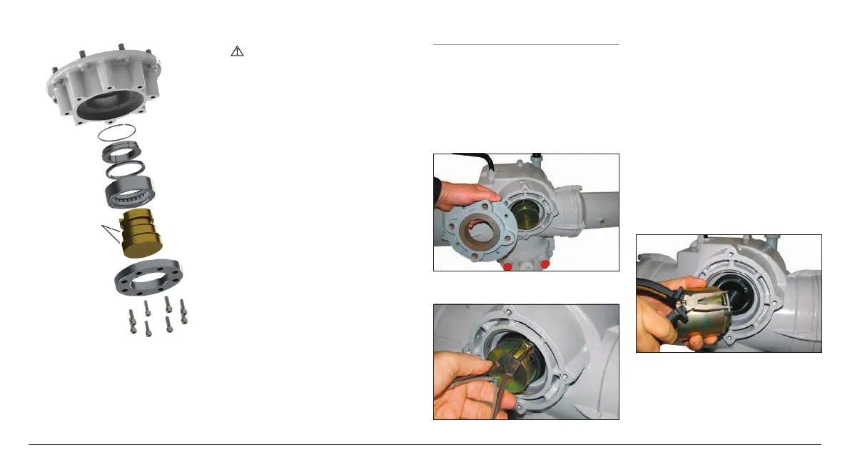
5.2 Non-Thrust Base Type B
All Sizes
Undo the hex head bolts securing the
base plate to the gearcase and remove
the base plate.
The drive bush and its retaining clip can
now be seen. The plate will vary with
the size of the actuator. See Fig. 5.2.1.
Fig. 5.2.1
Fig. 5.2.2
Types B3 and B4 Removal
Using external circlip pliers, expand the
circlip while pulling on the drive bush.
The drive bush will detach from the
actuator centre column with the circlip
retained in its grove. Refer to Fig. 5.2.2.
Types B1 Removal
The procedure for removal and refitting
of the B1 drive bush is the same as
for B3 and B4, however the circlip is
replaced with a custom spring circlip.
The spring operates in the same
manner as the B3/B4 circlip but is
expanded using long nose-pliers. Refer
to Fig. 5.2.3.
Fig. 5.2.3

 Loading...