18 IQ3 manual – Section: Cable Connections
WARNING: Ensure all power
supplies are isolated before
removing actuator covers.
Check that the supply voltage agrees
with that stamped on the actuator
nameplate.
A switch or circuit breaker must be
included in the wiring installation or
the actuator. The switch or circuit
breaker must meet the relevant
requirements of IEC60947-1 and
IEC60947-3 and be suitable for the
application. The switch or circuit
breaker must not disconnect the
protective earth conductor. The switch
or circuit breaker must be mounted as
close to the actuator as possible and
shall be marked to indicate that it is the
disconnect device for that particular
actuator. The actuator must be
protected with overcurrent protection
devices rated in accordance with the
applicable electrical data publication:
• PUB002-099
(3-phase actuators)
• PUB002-019
(single-phase actuators).
• PUB002-120
(3-phase modulating actuators)
• PUB002-121
(DC actuators)
WARNING: Actuators for use on
phase to phase voltages greater
than 600 V must not be used on
supply systems such as floating, or
earth-phase systems, where phase
to earth voltages in excess of 600
VAC could exist.
Power supply cables must have sufficient
mechanical protection properties to meet
installation requirements and be screened
to comply with EMC requirements of
the installed actuator. Suitable methods
include armoured and/or screened cables
or cables contained within conduit.
7.2 Earth/Ground Connections
A lug with a 6.5 mm diameter hole is
cast adjacent to the conduit entries for
attachment of an external protective
earthing strap by nut and bolt. An
internal earth connection is also provided
however it must not be used alone as
the Protective Earth Connection.
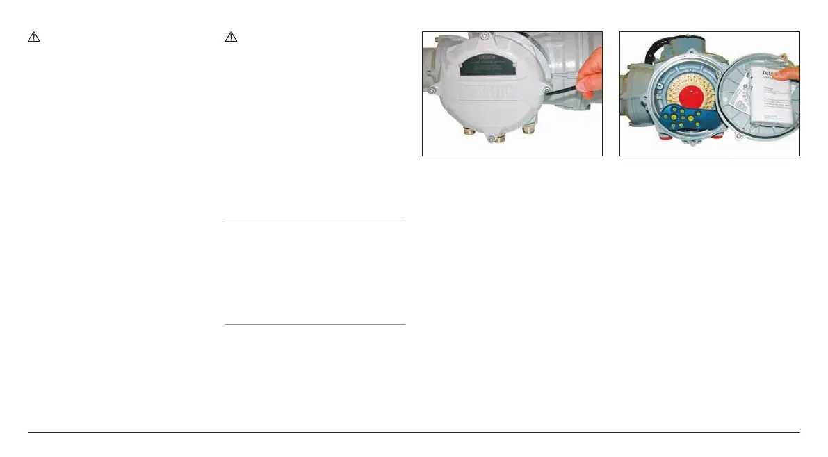
7.3 Removing Terminal Cover
Using a 6 mm Allen key loosen the four
captive screws evenly. Do not attempt
to lever off the cover with a screw
driver this will damage the O-ring seal
and may damage the flamepath on a
certified unit.
Fig. 7.3.1
The Rotork Bluetooth setting tool is
packed separately, with the actuator,
in the shipping box identified with a
yellow label.
The wiring code card fixed in the cover
is particular to each actuator and must
not be interchanged with any other
actuator. If in doubt check the serial
number on the code card with that of
the actuator.
Fig. 7.3.2 Actuator terminal compartment
and bluetooth Setting Tool Pro (Packed
separately in shipping box).
A plastic bag in the terminal
compartment contains:
• Terminal screws and washers.
• Spare cover O-ring seal.
• Wiring diagram.
• Instruction book.

 Loading...