IQ3 manual – Section: Operating your IQ Actuator 9
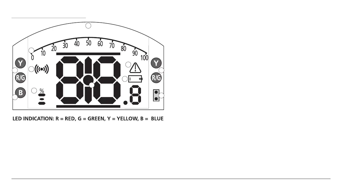
4.3 Display - Local Indication
1
2
3
44
5
6
7
8
9
10
Fig. 4.3.1 Segment Display
1. Position display
This is the main segment display for
position and torque; position indication
to 1 decimal place.
2. Analogue Scale
Scale 0% to 100% is used when
Analogue torque (% of rated) or
Positioning (% position / demand)
homescreens are selected. Refer to
section 4.4.
3. Infra-red LEDs
Used for older models of setting tool
and to initiate a data connection using
Bluetooth wireless technology.
4. Dual position LEDs
Consisting of 2 x Yellow for mid
position and 2 x bi-colour (Red / Green)
for end of travel indication.
5. Bluetooth indication LED
A dual intensity LED for indicating an
active connection using Bluetooth
wireless technology.
6. Alarm Icon
This will be displayed for valve, control
and actuator alarms. Alarm indication
is supported by fault description in the
text in the line above the main display.
7. Battery Alarm Icon
This icon will be displayed when
a battery is detected as low or
discharged. "Battery low" or
"Discharged" will also be displayed in
the text display above.
8. Infra-Red Icon
This icon flashes during setting tool
communication activity. LEDs will also
flash when keys are pressed.
9. Percentage Open Icon
This icon will be displayed when an
integer open value is displayed e.g.
57.3.
10. Dot Matrix Display
A high resolution 168x132 pixel
display for displaying setup menus and
datalogger graphs.
When a positional display is active,
the status and active alarms will be
displayed.
The LCD screen is made up of two
layers; the main segment display and
the dot matrix display. The displays
are dual stacked so that either display
can be enabled to show different
information. This also allows a
combination of both displays for added
flexibility.
On power the LCD is backlit with a
white light to enable the best viewing
contrast in all lighting conditions. For
additional positional indication, the
LEDs at either side of the LCD are used
for Closed (green), mid-travel (yellow)
and Open (red) as standard. These LEDs
are fully configurable in the settings
menu or on request at time of order.

 Loading...