3.1.4 Inside a CMA actuator
The FF CP is suitable for fitting into CMA actuators, wiring diagrams MXX-FX (where X can be any
value) detail the option card connections on the terminal strip. The FF CP module is fitted in the only
option board slot inside the CMA electrical housing.
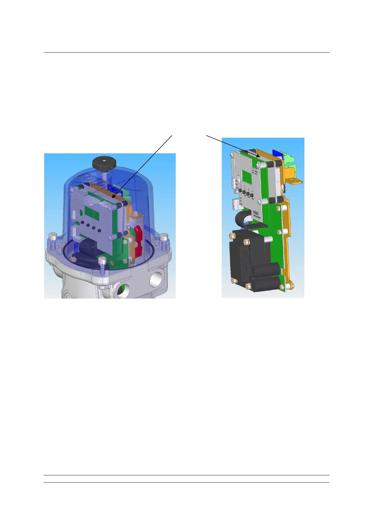
Fig 3.4: The FF CP located in a CMA actuator
The FF CP should be replaced or fitted only in a suitable environment. The actuator must be made
electrically safe before opening any covers. The electrical housing cover should be removed after
unscrewing the four 6mm Allen machine screws.
The FF CP should be fitted in the position shown in the illustrations above. It plugs into the control
board at the 10-way header, which is SK2 on the FF CP board. There is a wiring loom which brings
the FF H1 network connection to SK3 on the FF CP.
Connection details are shown in the illustrations on the next page.
The CMA actuator will need configuring, so that it is aware that control from the field is through the FF
CP card. This is done by accessing the menu structure as shown in the CMA Installation and
Maintenance manual, PUB094-003, found on the Rotork web site.