Actuator Input Output Signals
Publication PUB089-005-00_0618 27 of 116
5 THE ACTUATOR INPUT AND OUTPUT SIGNALS
The FF CP card provides feedback data about its status and that of the actuator to the Foundation
highway. This data is contained in the Transducer function block and is fully listed in the section on
Function Blocks. The actuator is normally controlled by signals from the Foundation highway
connecting to the Output blocks and the Transducer block. There are local controls on the actuator
itself and there is the possibility to wire in direct contacts to control the movement. This section
explains the primary data available and the meaning of the signals generated by the actuator.
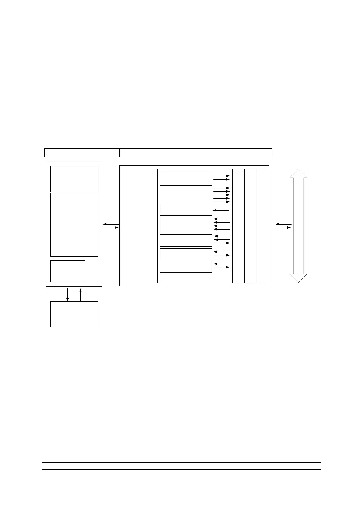
Actuator FF CP card
Motor &
Starter
Controls
Actuator
Control PCB
Local
Controls
Hard-wired
Control Inputs
& Outputs
Actuator
Interface
2 x AI
5 x DI
4 x DO
1 x PID
1 x CS
1 x Transducer
1 x Resource
Fieldbus Message Specification
Fieldbus Access Sublayer
Data Link Layer
1 x AO
FF H1 Data Highway
Input signals are those returned by the actuator to the network about the status of the actuator and
valve whilst output signals are those used to command the actuator to move or operate its internal
relays. An actuator control signal such as a command to open is an output, whilst a reported status
such as open limit switch reached is a feedback input.
Fig 5.1: Actuator and FF CP Card Block Diagram