4.2 Fieldbus power supply
The FF card takes power from the H1 data highway. This means the internal function blocks are
available for control connection between devices even when the actuator has no power.
The power is taken from a special DC power supply connected onto the network through a suitable
filter. The power consumption of each FF node on the network is 20 mA and the absolute minimum
voltage at the actuator terminals is 9 volts. The power supply has to contain an inductive network to
prevent attenuation of the fieldbus signal by the low impedance of the power supply itself. The
inductive network in the power pack makes sure that its equivalent impedance is quite high at the
31.25 kbits/sec frequency whilst still allowing a DC current to be drawn for the line-powered devices.
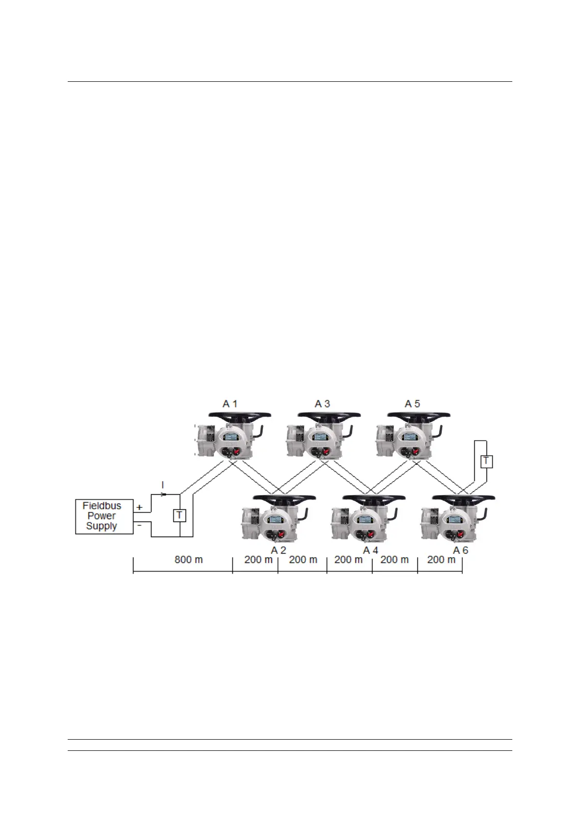
Since each node on the fieldbus consumes power from the DC supply, great care must be taken in the
design of the installation. The design must ensure that the volt drop from the power pack to the
actuator still leaves at least 9V (absolute minimum) for the FF card and ideally at least 10 Volts. The
actuators can withstand a maximum voltage of 32V from the power pack and since the current
consumption is virtually constant, a simple Ohm’s law calculation can be used to determine the
potential at each point in the network. On power up there is no additional inrush current, i.e. the inrush
current value is the same as the nominal.
The Foundation fieldbus wiring guide (AG -140) provides examples of how to calculate the voltage at
each point.