Note: Ensure that parameters 65 (Control Mode) and 66 (Discrete Block Control) in the
Transducer block are set for the type of control and DO 4 mode required.
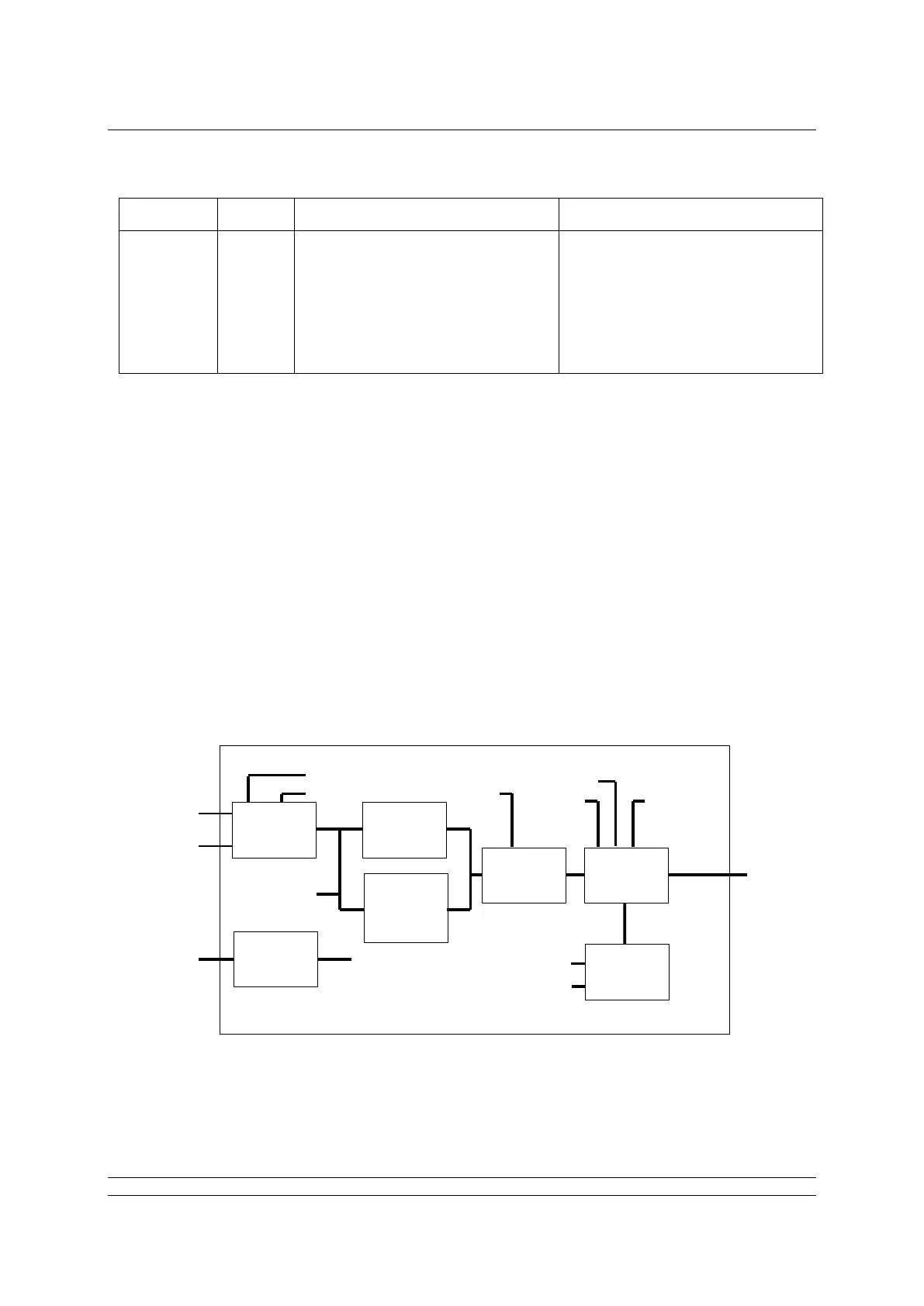
6.7 PID Control block
The actuator includes a standard three-term PID controller block for use in a control loop. The inputs
and outputs of this block are not directly linked to the actuator Transducer block. This allows the PID
controller to be used for controlling devices other than the actuator. With a PID function, as long as an
error exists between the set point (desired value) and the measured value feedback (process
variable), the controller will change the output in a direction to reduce the error.
The way in which the output changes is influenced by the actual error value, the time it is present and
the rate of change it undergoes. The PID settings applied integrate the error with respect to time
(RESET value), apply a proportional gain on the error (GAIN) and differentiate the rate of change in
the error (RATE); all these actions are combined to produce the OUTPUT.
PID A stand-alone 3-term controller within the actuator.
The PID block must be connected and set up before it can be used. It is not pre-connected to any
input or output of the actuator transducer block and may be freely connected into a control loop. The
scheduler is used to allocate a time slot for the control algorithm to execute.