3 FITTING THE FF CP CARD
3.1 Inside a Rotork Actuator
3.1.1 Inside an IQ3/IQT3 actuator
The FF CP card is suitable for fitting into IQ3 actuators. When factory-fitted, their wiring diagrams will
contain an ‘F’, e.g. 100F2000. The FF CP can be located in one of 2 or 4 option ‘slots’ located on the
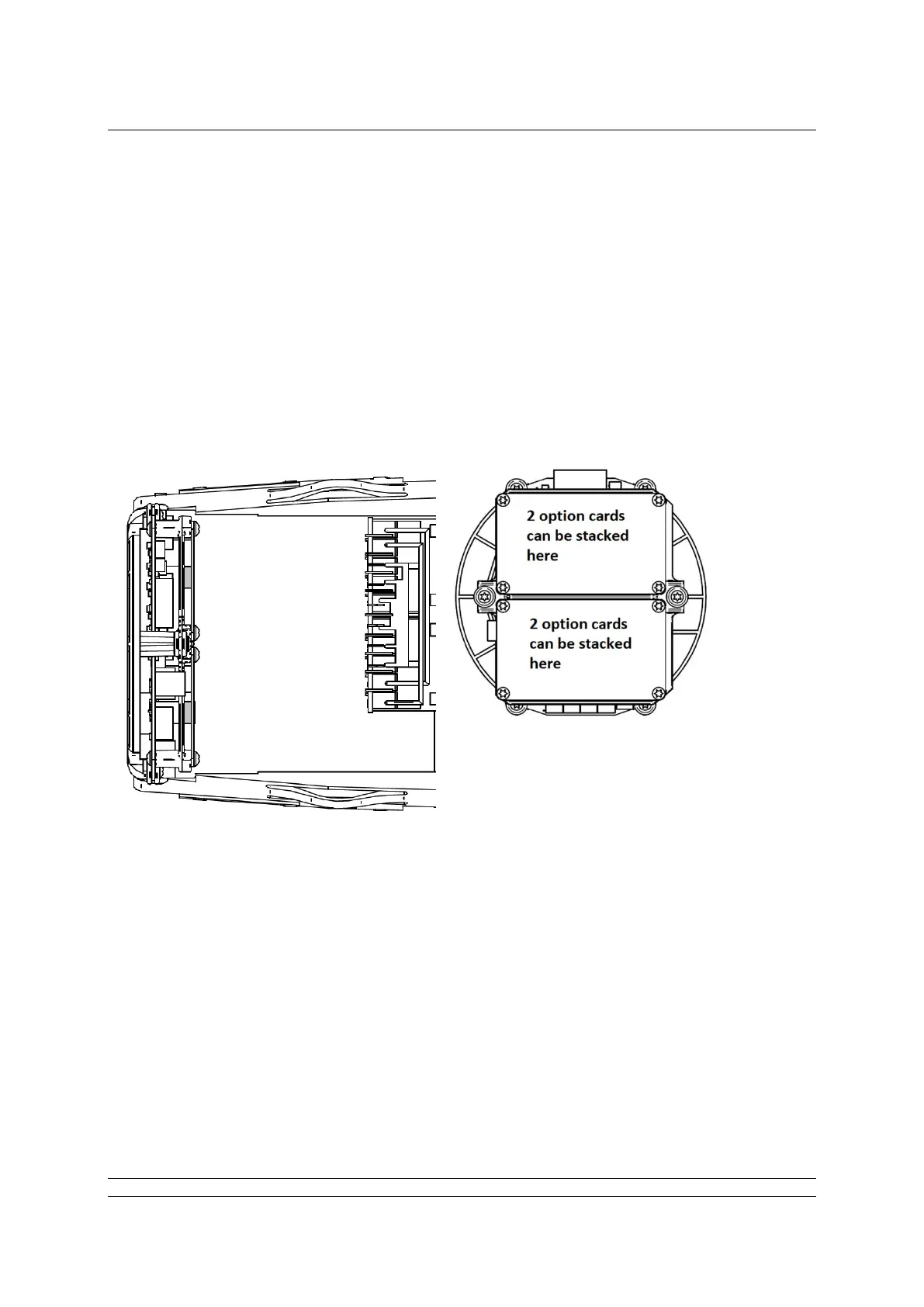
back of the control module PCB, housed in the electrical cover. There are 2 slots for directly
connecting the option module to the control module and where those slots are already filled, the option
card can be fitted on top of the existing modules. The modules can be stacked 2 high where a ‘deep’
electrical cover is fitted.
Back of the control module
Fig 3.1: The FF CP card’s location behind the control module in an IQ3
With the IQ3 actuators, the remote inputs are always present (they are conditioned by the control
board) and there is an option to include Digital Outputs from relay contacts. If the FF CP is required to
operate the 4 digital outputs that can be controlled from the card, then an Extra Relay Indication card
associated with these outputs must be fitted into another option slot in the actuator.
The FF CP is connected to the control module by a 10 way header (SK2). The wiring harness from the
actuator terminal bung connects the FF H1 highway field connections to SK3.