Actuator Input Output Signals
Publication PUB089-005-00_0618 63 of 116
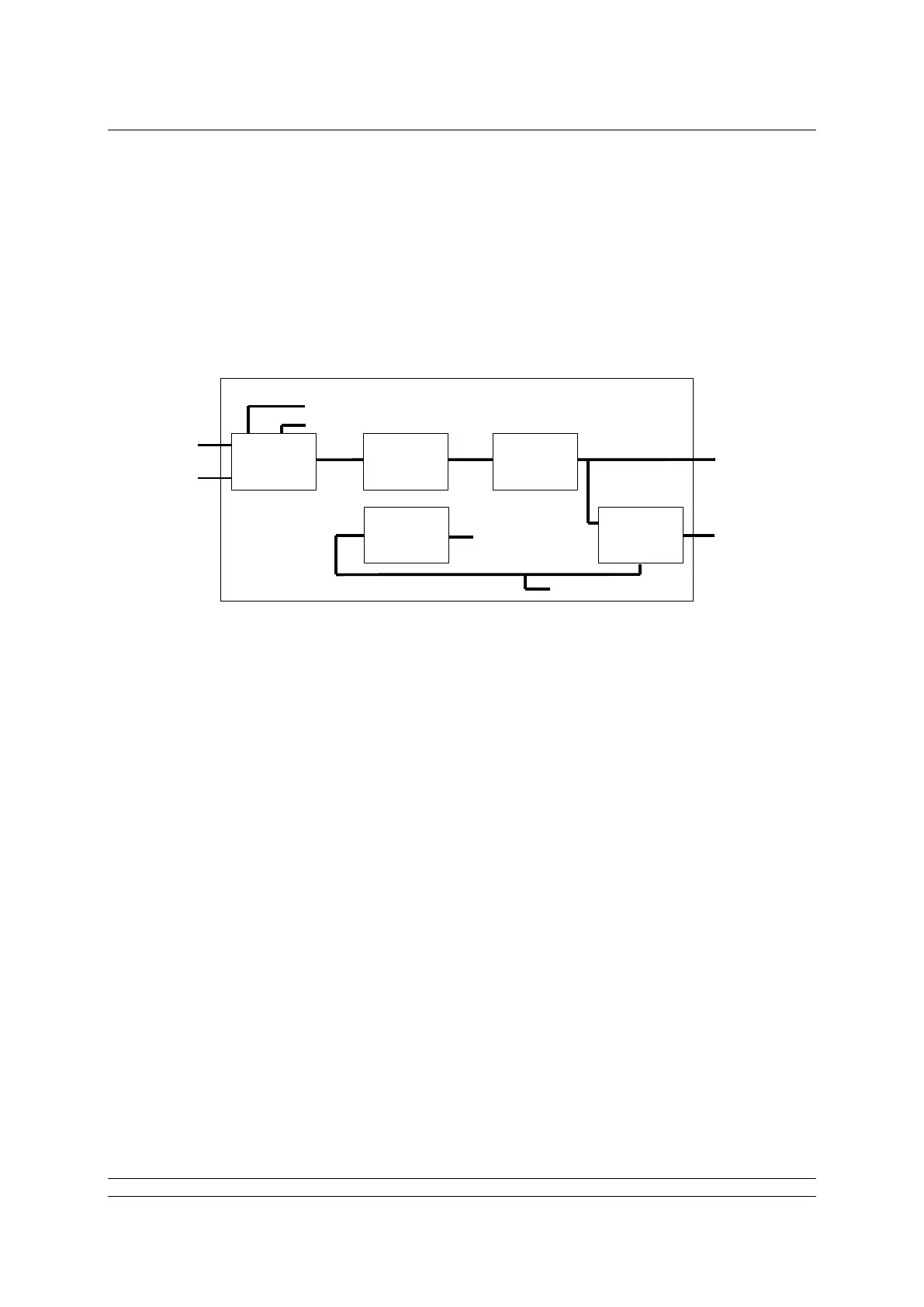
6.5 Analogue Output block
There is one Analogue Output (AO) block in the FF CP that is designed to allow the valve under
control to be positioned to a specific value over its position range of 0.0-100.0%.
A0 1 The % set point (position) of the valve. The range is 0.0-100.0% and the end
values relate to the close (0%) and open (100%) position limit switches.
Actual resolution is 0.1%, but the practical resolution is 1%
Positioning accuracy is dependent upon deadband and hysteresis settings
On installing the card, the following settings will apply:
The output connections to the Transducer block are fixed and in place.
The Mode control is standard (Auto, Man, LO, OOS).
When the actuator Local/Remote selector is not in the Remote position the block will
adopt LO mode.
The IO_OPTS must be set to PV for BKCal_Out.
In the resource block set Feature select to Out_Readback
AO is channel number 8 (this must not be changed).
For the correct operation of the AO block, the setting IO_OPTS = PV for BKCal_Out should be
performed in the function block during the configuration of the Foundation Fieldbus. This setting is
found within the AO function block dialogue box in the options folder, as shown in Fig 25. Setting it to
this value ensures that the BKCal_Out value follows the actual valve position if the actuator is moved
manually, by the local controls or by other electrical means.