EasyManua.ls Logo

rotork Mk3 - Multiple Block - Single Bit Control; Single Block - Multiple Bit Control

rotork Mk3
116 pages
Print Icon
To Next Page IconTo Next Page
To Previous Page IconTo Previous Page
Loading...
Foundation Fieldbus CP Option Card Technical Manual
66 of 116 Publication PUB089-005-00_0618
Fig 6.10: DO4 options as shown in the TB
Note: Mode 6 bit 0 is position control enable.
6.6.1 Multiple block single bit control
DO 1 Bit 0 = ‘Close’.
DO 2 Bit 0 = ‘Open’.
DO 3 Bit 0 = ‘Stop’.
DO 4 Bit 0 = selected by mode see below.
* Note:
1. Mode 0 and mode 6 offer the same
control in single bit support. When used in
multistate support, mode 6 provides both
position control enable and PST options in
the same block.
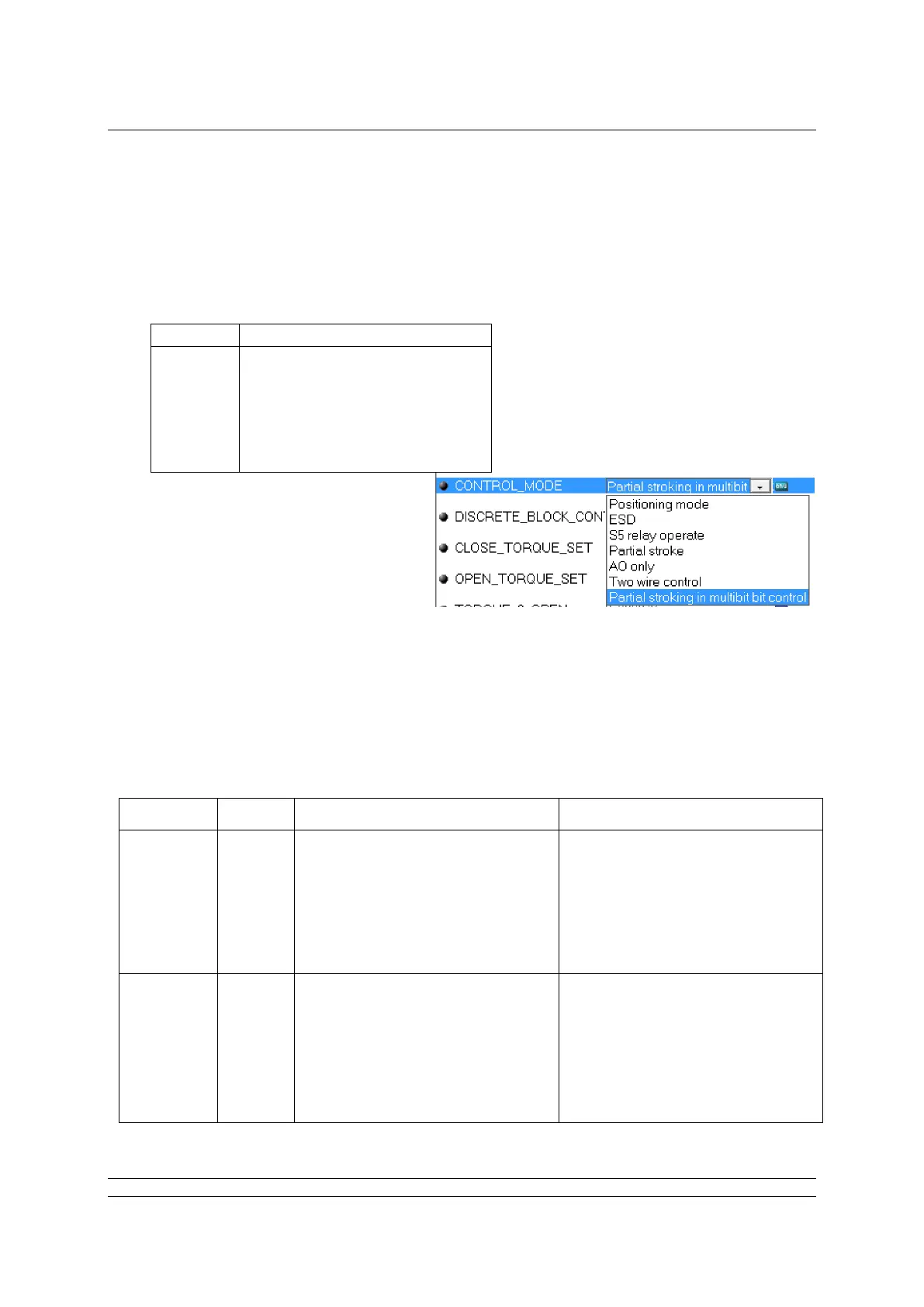
2. The DO4 block options will appear as
shown in fig 6.10
6.6.2 Single block multiple bit control.
The table below identifies the function of each bit in the available DO block when multiple bit control is
selected. PV_D comes from READBACK from the appropriate ‘status inputs’. The bold text in the
read-back column below indicates bits that only echo the command operation. The italic text in the
operation and read-back column show the function of the block for the multiple block mode described
previously.
Block
Bit
Operation
Read-back
DO 1
0
1
2
3
4
5
6
7
Close
Open
Stop
ESD
Position control enable
Set relay 1
Set relay 2
Set relay 3
Close limit
Open limit
Actuator not moving
ESD
Position control enabled
relay 1 set
relay 2 set
relay 3 set
DO 2
0
1
2
3
4
5
6
7
Open
Close
Stop
ESD
Partial stroke
Set relay 1
Set relay 2
Set relay 3
Open limit
Close limit
Actuator not moving
ESD
Partial stroking
relay 1 set
relay 2 set
relay 3 set
Mode
Bit 0 Function
0
Position Control Enable *
1
ESD
2
Set/reset relay 1
3
Partial Stroke *
4
Not Applicable (AO only control)
5
6
0= close, 1 = open
Position Control Enable *

Table of Contents

Related product manuals