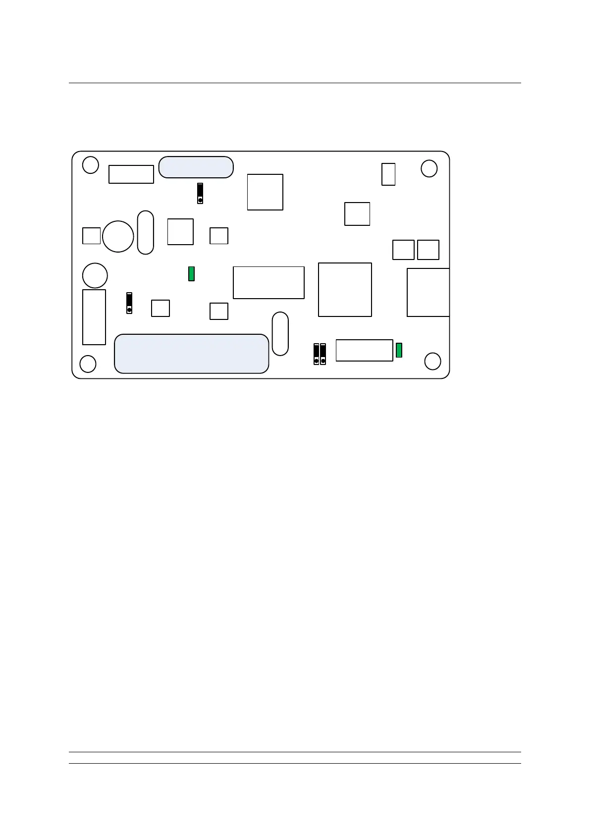
The FF CP card includes two connectors (SK1 and SK3), two LED indicators (LED1 and 2) and four
jumpers, (JP1 – 4). The position of these jumpers should not normally require alteration from the
factory default positions. The illustration shows the default positions. The LEDs can be used to help
with system diagnostics in some cases.
The function of each connector, LED and jumper is as follows:
SK1 This socket connects the FF CP card to the actuator’s control PCB via a CANbus
highway
SK3 This socket connects the FF CP card to the FF highways via the actuator’s
terminal bung connections.
Note there are two other connectors which are used to program the FF CP card and which are
not described in this document
LED 1 Indicates the FF CP Card is communicating with the actuator’s control PCB.
LED 2 When flashing, this Indicates there is an active connection to the fieldbus highway.
When on (i.e. not flashing), this indicates the fieldbus highway power is present.
 Loading...

