6 FUNCTION BLOCKS
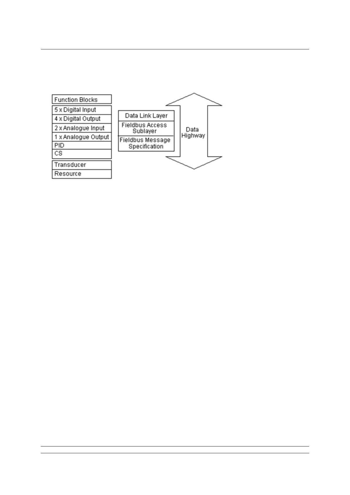
Function blocks provide the heart of the Foundation Fieldbus system. Each device on a network
includes at least one Transducer block and a Resource block to allow the equipment to be configured
to operate on the network.
The FF CP card includes 16 blocks, of which one is the Resource block and one is the Transducer
block. The remaining 14 input and output blocks are used to control and collect data from the actuator.
In order to make the FF CP easier to use, all of the parameters in the blocks are already defined. The
Foundation requires certain parameters to be set to specific default values. The actuator controller will
require the alteration of some of these when a particular function block is to be used. The values can
be altered using a suitable configuration tool. Some of the network communications link location data
(VCR coding) are already defined, as required by the Foundation specifications. Publisher and
Subscriber function blocks have VCR values assigned, as described in the DD file. The pre-assigned
connections that are fixed include:
The two AI blocks to the two analogue input variables in the actuator.
The AO block to the resident analogue output positioner in the actuator.
The four DO blocks to the digital outputs for controlling the open/close actions of the
actuator.
The five DI blocks to the digital inputs for reporting actuator status to the network.
Many of the features of the function blocks are provided in order to allow the system to automatically
identify and use these blocks. The Fieldbus specification FF-890 to FF-892 defines all aspects of the
function blocks. In practice, the user needs to know very little about the internal workings of the blocks,
as the Capabilities file lists all the available features. A suitable configuration tool such as that supplied
by National Instruments can be used to set up all the tag names and operation of the blocks in the
complete system. The contents of the blocks can also be examined using a configuration tool. Most
DCS systems include configuration utilities for Foundation Fieldbus devices.
Each block must have its own unique tag name allocated during system configuration and each block
has at least three modes it can be in, which show its availability on the system (OOS – Out Of Service,
Auto – local set point used for the primary output value algorithm, CAS – set point value from the Cas
input is used for the primary output value algorithm).