Appendix
Publication PUB089-005-00_0618 93 of 116
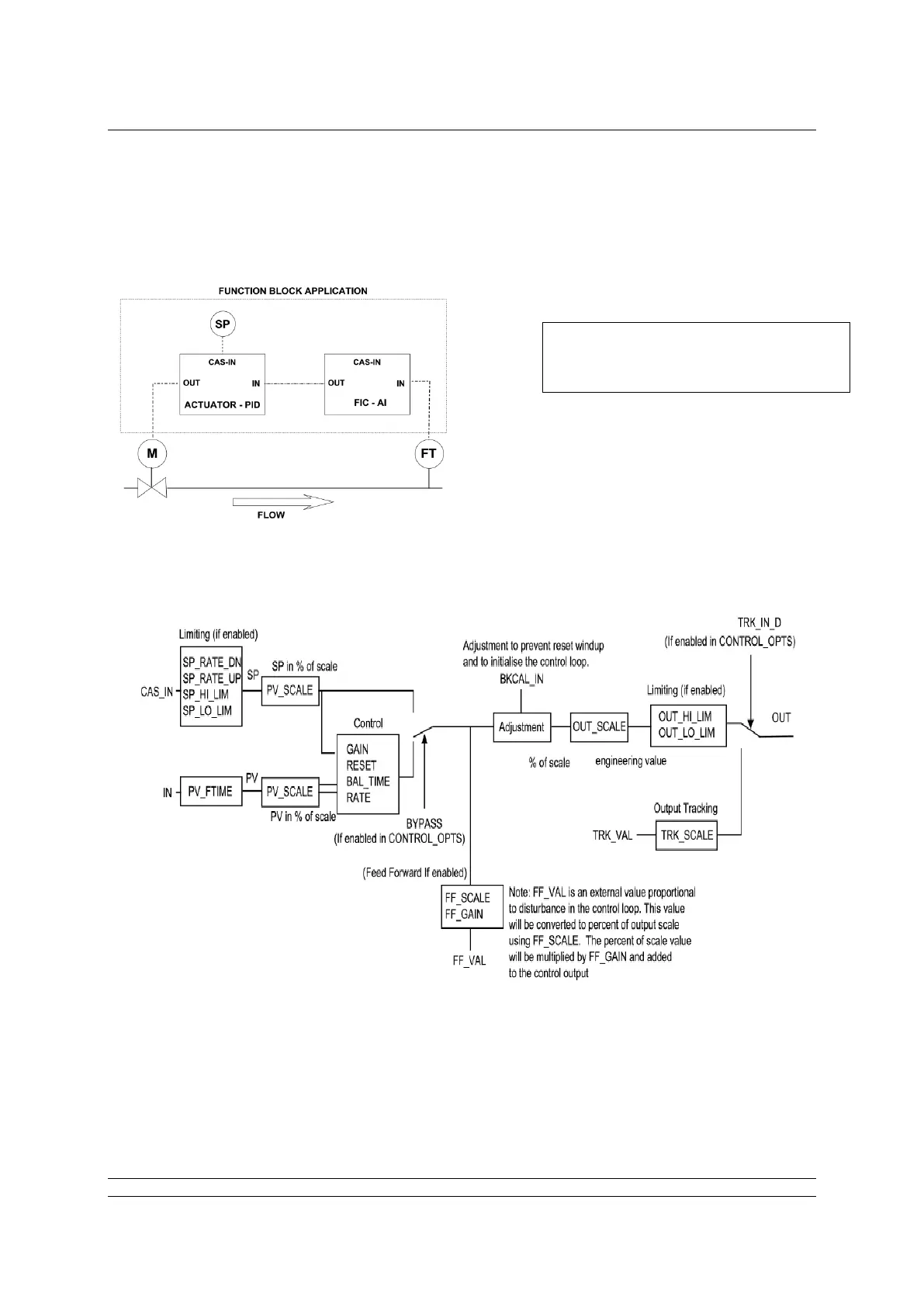
APPENDIX C – PID APPLICATION.
Fig C.1: PID example.
The diagram above illustrates the settings available in the PID such as PV_SCALE (Process variable
scaling factor) and the interdependencies that occur with, in this case, PV and SP. By using the block
diagram it should be possible to ‘scale’ the PID to achieve the required control regime.
In this example, a flow transmitter FT
provides a measurement (PV) which is
required to position an actuator M (OUT)
to maintain the required process flow
with respect to a set point (SP).
Diagram of the PID Function
Block showing the relationship of the
various parameters.