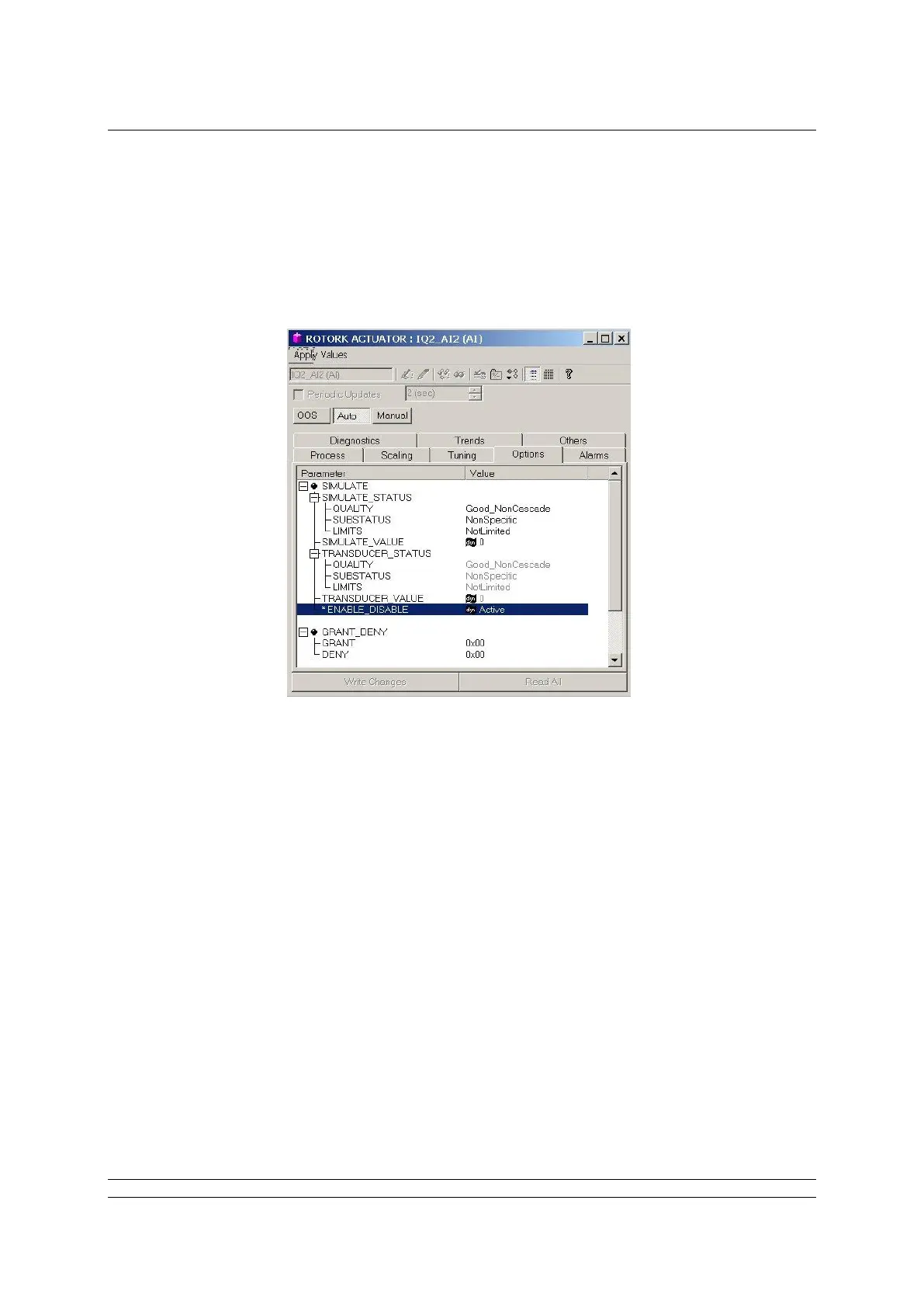
JP1, Simulation In simulation mode, the user is permitted to write to primary input/output
Mode Jumper actuator variables through the status and value attributes normally written to
by the transducer block. With JP1 ‘On’ a function block may have its simulation
‘active’ parameter enabled. When JP1 is ‘Off’ the primary actuator variables are
not write enabled. The normal position is ‘Off’, as shown on the schematic above.
See the appendix section for more information on simulation mode operation.
JP2, Hard-Write A setting can be made in the ‘FEATURE_SEL’ parameter of the Resource block
Lock which prevents the writing/changing of all configuration parameters in the FF CP
card. If the FEATURE_SEL is set to ‘Hard W Lock’, the jumper function becomes
write protect ‘On’ and ‘Off’. (See section 6.1 Resource Block). The normal position
is ‘Off’ as shown above.
JP3, CANbus This must be left in the “Off” position as shown in the fig 9 above
Terminator
JP4, Slot 0 / 1 In fig 3.7, this is shown in the slot 0 position. The jumper is moved to the slot 1
Selector position when two FF CP cards are fitted into the same actuator and one of them
already has slot 0 selected.