© Safe Fleet | 2020 | All rights reserved | Part #: 700-1234 R1
DH4 Installation Guide
p. 42
DH4 Advanced Conguration
G-Sensor
Conguring G-Sensor Options
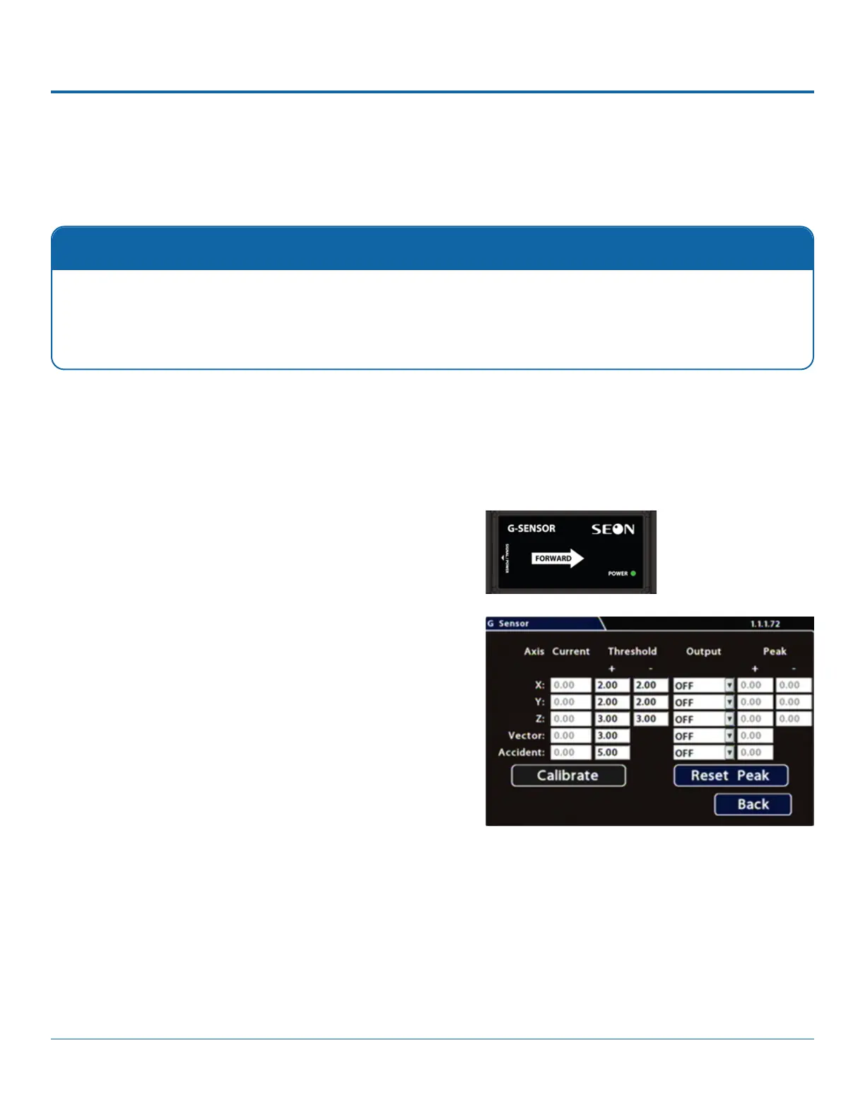
i. Ensure the G-Sensor unit is mounted securely with the
arrow toward the front of the vehicle. The orientation of
the device has no impact on its performance provided
that the arrow has been appropriately pointed towards
the vehicle's front.
The unit connects to the G-SENSOR port on the DVR rear
panel. For more information see the DH4 Quick Install
Guide
ii. Click Calibrate.
The X, Y, and Z axis planes are set, based on the
mounting surface. When the process is complete, click
3. If required, adjust G-Sensor settings. For details, see Menu
Options, below.
4. Click Back to save settings, then click Back again to return to
Calibration
The G-Sensor must be calibrated when initially installed or if the unit is relocated, and the procedure must be per-
formed on the vehicle (i.e. not by connecting to the DVR from a remote location).
enabled, many alarms may be generated. Details are provided below.
1. Select Alarm/Signal G-Sensor to open the tab.
2. If this is a new system installation, or the G-Sensor unit has been relocated, perform the following Calibration
procedure: