5-001
ELECTRICAL SYSTEM
1. PRECAuTIonS foR woRk
1-1. Wire Numbers, Wire Sizes, Wire Colors and Connectors Shown in
Electrical Circuit Diagram, Wiring Harness Layout and Wiring Harnesses
Codes used in electrical circuit diagrams give the following information.
The wire size is AVS 0.85 unless otherwise specied.
AVS Size
Type of terminal
Wire color
(Indicated inconnectors
in case of wires)
Wire number
38
3LY
9
2BrW
2BrW
9
38
58X-2M
3LY
70
Type of terminal
Marking "C"
63
9
GB
Brw
38
LY
SWP-4M
C C
Marking
Corrugate
120
Protection
between
Wire
number
Length
between
50
CorrugateǞ70
GB,100
CB104
58X-2F
200
Ǟ13
770
63
CorrugateǞ10
*
*
Brw
9
*
*
GB
63
LY
38
SWP-4㧲
Mark S
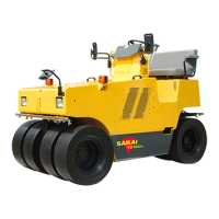
Starter relay harness
(P.5-017)
J
(P.5-005)
(BrR),(GL)
Fuel sensor
Wire color
Reference page
Marking
Reference page
24 1.25 BR
Wire color
AVS wire size
Wire number
7
28 LgW
R2
BR
R1
C
B
ACC
24 1.25BR
4
26 Lg
STARTER
SWITCH
26 Lg
5G
5BY
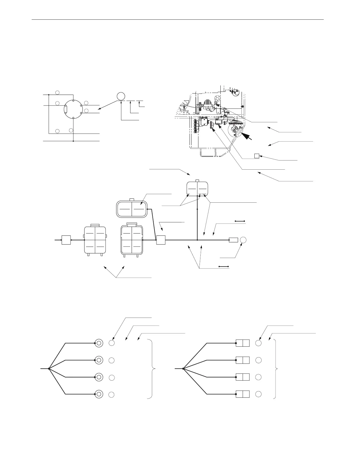
The pin or socket layout of mating connectors are symmetrical, either vertically or horizontally. When the
connector valves are connected, the pin and socket that have the same number are connected.
Switch terminal number
Wire number
Terminal type
Switch terminal number
Wire number
WG,150
(3)
(1)
BW,150
(5)
(4)
Throttle switch
RY,150
RW,150
94
93
30
97
1.25LgW,70
LA105
5BY,70
LA305
BR,70
LA105
2Lg,70
LA205
(ACC)
(B)
(BR)
(C)
4
24
26
28
Starter switch
•
•
•