4-001
HYDRAULIC SYSTEMS
1. SYSTEM CIRCUIT DIAGRAM
1-1. Graphic Symbols for Hydraulic Circuits
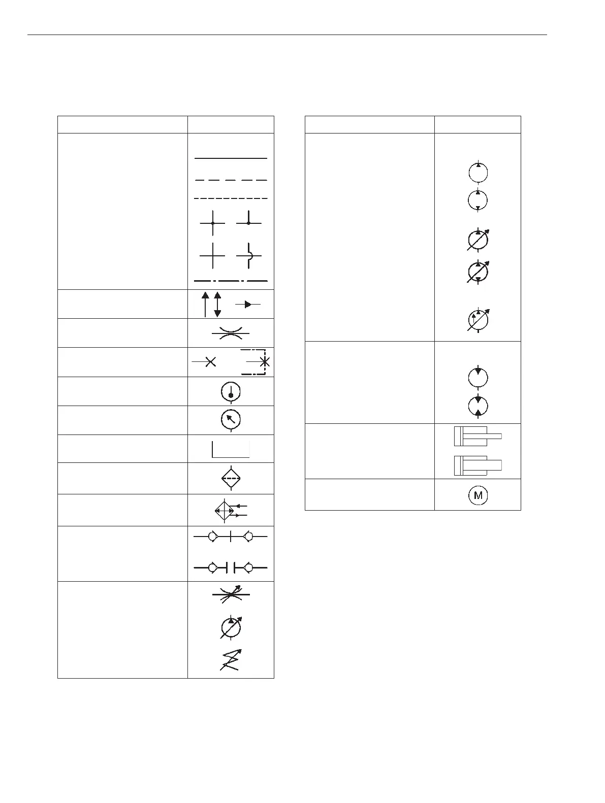
Basic Symbols
DESCRIPTION SYMBOL
Lines:
Main working
Pilot control
Drain or bleed
Lines, joining
Not connected
Component outline
Arrow indicates direction
of ow.
Line with xed restriction
(orice).
Test port, pressure
measurement.
Temperature measure-
ment gauge
Pressure measurement
gauge
Reservoir (vented)
Filter or strainer
Heat exchanger, lines in-
dicate ow of coolant.
Quick disconnect:
Connected with mechan-
ically opened checks.
Disconnected.
Sloping arrow through a
symbol at 45° indicates
that a component can be
adjusted or varied.
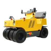
Pump, Motors and Cylinders
DESCRIPTION SYMBOL
Hydraulic pumps:
Fixed displacement
Unidirectional
Bidirectional
Variable displacement
Unidirectional
Bidirectional
Variable displace-
ment pressure com-
pensated
Unidirectional
Hydraulic Motor:
Unidirectional
Bidirectional
Double acting hydraulic
cylinder
Differential cylinder
Electric motor