4-013
HYDRAULIC SYSTEMS
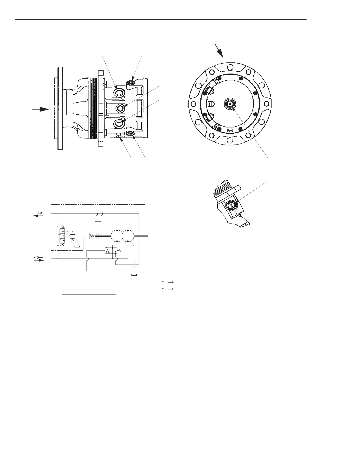
2-2-2. Propulsion hydraulic motor (F) (SW/TW354)
4
1
2
5
1
2
3
4
5
6
8
7
Motor circuit diagram
VIEW B
4 1 Clockwise rotation
1 4 Counterclockwise rotation
Flow of oil (Rotation direction is when
viewed in direction of arrow A.)
3
6
7
X
(1) Port B [FMB] : G1/2 (5) Parking brake pilot port [FM3] : G1/4
(2) Parking brake pilot port : G1/4 (6) Speed change port [FM4] : G1/4
(3) Drain port [FMD] : G3/8 (7) Manual brake release port : M10
(4) Port A [FMA] : G1/2 (8) Charge relief valve
Specications
Displacement• : 465 cm
3
/rev ( 28 cu.in./rev )
Maximum working pressure• : 34.3 MPa ( 4,974 psi )
Charge relief valve pressure setting •
: 1.67 to 1.86 MPa ( 242 to 270 psi )
Allowable motor case pressure• : 0.3 MPa ( 43.5 psi )
Brake release pressure• : 1.5 MPa ( 218 psi )
Weight• : 42 kg ( 93 lbs. )
 Loading...