9-025
INSPECTION AND ADJUSTMENT
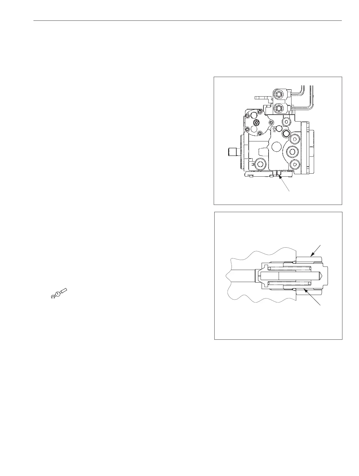
16-2. Adjustment
If measurement results indicate the pressure deviating from
standard charge relief pressure setting range, make an
adjustment in accordance with procedure described below.
①
Check nut (1) of charge relief valve (15) for evidence of
having loosened.
②
If there is evidence of nut having loosened, adjust charge
relief valve so that pressure becomes within standard
charge relief valve pressure setting range while watching
pressure gauge.
To adjust pressure, loosen nut and turn adjustment screw
(2).
Adjustment screw turned clockwise
: Pressure rise
Adjustment screw turned counterclockwise
: Pressure drop
Pressure change rate : 0.19 MPa/turn (27.6 psi/turn)
③
If there is no evidence of nut having loosened, remove
charge relief valve.
④
Check removed charge relief valve for trapped dirt and
scratches on its seat.
⑤
If trapped dirt is present, disassemble and clean charge
relief valve.
⑥
If a scratch is found on seat, replace charge relief valve.
⑦
After adjustment, measure pressure again and check that
pressure reaches standard charge relief valve setting
range.
(1) Nut : 24 N·m (18 lbf·ft)
(NOTICE)
Carefully disassemble and reassemble after taking
steps to prevent foreign material from getting in.
The number “15” appearing in above illustrations is consistent with lead line numbers shown in illustration of
propulsion pump in “6-2. Hydraulic Component Specications” (page 4-034).
•
•
•
•
SW504
 Loading...