SAMWONTECH
1st Edition of TEMP880S IM : Sep. 21. 2005 Page 31 / 101
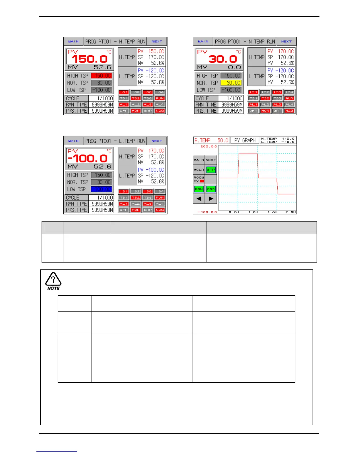
Diagram 2-18. Program Operation–2screen Diagram 2-19. Program Operation-2screen
(High temperature room operation) (Normal temperature room operation)
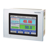
Diagram 2-20. Program Operation-2screen Diagram 2-21. Program Operation-3screen
(Low temperature room operation)
No. Instruction Contents Additional Explanation
○
1
AUTO TUNING
KEY
Displayed when setting a tuning
button of a screen for screen
selection of (Diagram 2-40) as
DISP.
WAIT SP
High Temperature Room
(HIGH TEMP ZONE)
Low Temperature Room
(LOW TEMP ZONE)
No Setting
High Temperature Room PV =
Preheating SP
(H.PV = WAIT SP)
Low Temperature Room PV =
Precooling SP
(L.PV = WAIT SP)
Setting
Preheating SP – Preheating Deviation
≤ High Temperature Room PV
≤ Preheating SP + Preheating
Deviation
(H.WAIT SP – H.WSP.DEV ≤ H.PV
≤ H.WAIT SP + H.WSP.DEV)
Precooling SP – Precooling Deviation
≤ Low Temperature Room PV
≤ Precooling SP + Precooling
Deviation
(L.WAIT SP – L.WSP.DEV ≤ L.PV
≤ L.WAIT SP + L.WSP.DEV)
Preheating SP : Setting value for preheating high temperature room
Preheating Deviation : Deviation value for preheating SP
Precooling SP : Setting value for precooling low temperature room
Precooling Deviation : Deviation value for precooling SP
WAIT(Preheating, Precooling) Removal Condition