Multi-Port Optical Power Meter MPM-210
3-1
Panel Descriptions
3
(1)
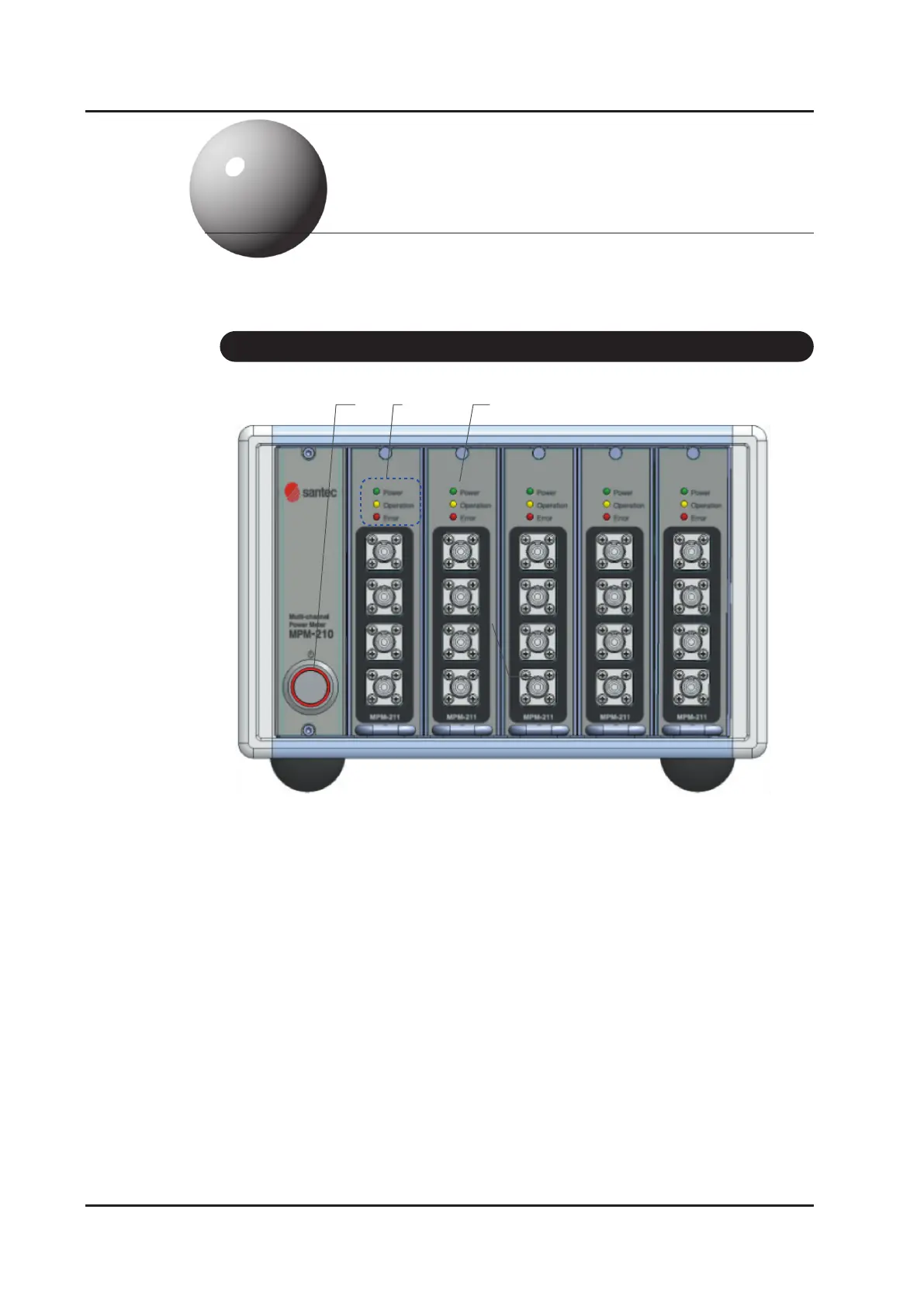
Figure 3-1.
Front Panel
(2) (3)
(4)
(1) Power on switch
(2) LED for Power, Operation and Error
Power LED light will be turned on when the product is on. Operation LED light
will be on while measuring and Error LED light will be on if the product is not
connected with main body internally.
(3) Module
Optical input port will be recognized as ports for measuring optical power and
it gets assigned as port numbers (1,2,3,4..) from top to bottom.
3-1 Front Panel