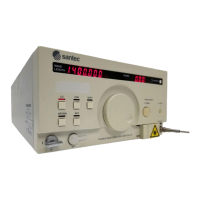
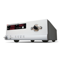
Multi-Port Optical Power Meter MPM-210
5-1
Remote Control
5
Item Command Default Address
Gate way Address GW 192.168.1.254
Subnet Mask SUBNET 255.255.255.0
IP Address IP 192.168.1.161
Remote port - 5000
CAUTION
Do not disconnect or connect a cable from and to devices connected with GP-IB
cable, do not short-circuit the connector, and do not turn ON/OFF the devices.
Otherwise, actions may be stopped or errors may occur, causing a failure. In
the event of such failure, reset all the connected devices, and then activate the
system once again. When configuring a system, remove the unused device or
unnecessary cable and return to the original setup.
MPM-210 exchanges information with controller by using GPIB, TCPIP or RS232
communication.
5-1 GPIB Communication
5-2 TCP/IP Communication
To set up for Gate way IP, Subnet Mask, IP Address, user needs to set them by RS232
communication or GPIB communication. (Refers to the 5.5.1.) When the MPM-210
receives the command, the terminator is recognized the <LF> and when the MPM-210
sends the command, the terminator is the <CR><LF>.
The MPM-210 supports IEEE488 interface. When receiving a command, it uses EOI
but not EOS. When sending a command, it uses EOI and EOS<CR>. Default value of
GPIB Address is 16.
Connect the 24-pin GPIB cable to the GPIB connector on the rear panel. The total
extension of the connected cable shall be 20 m or less. The cable length between
each device must be 2 m or less. At most, 15 devices can be connected.
CAUTION
Before inserting and extracting the connectors for the communication cables,
make sure to turn off power to the device to avoid damaging the device.
Default Conguration